Publication 1734-UM002C-EN-P - July 2003
1734-ADNX Quick Start B-19
This matches what you observed earlier on the main network:
• The data mapped in the 1734-ADNX will be exchanged with the
1756-DNB scanner.
• There are three memory buffers that the 1734-ADNX uses for
input data to the scanner on DeviceNet. The buffers are
Cos/Cyclic, Polled, and Strobed. You can map data into any of
the three buffer areas on the adapter.
• Currently, all of the I/O modules are mapped to the Cos/Cyclic
buffer.
2. Select the dropdown listbox next to the Memory label in the
middle of the window to display the three memory buffer
choices.
3. Select each of the choices and view the mapping. You will see
that only the Cos/Cyclic buffer is being used (There are 2 bytes
reserved for status in each buffer. These words are not for a
specific module.)
4. Set the Memory selection back to Cos/Cyclic.
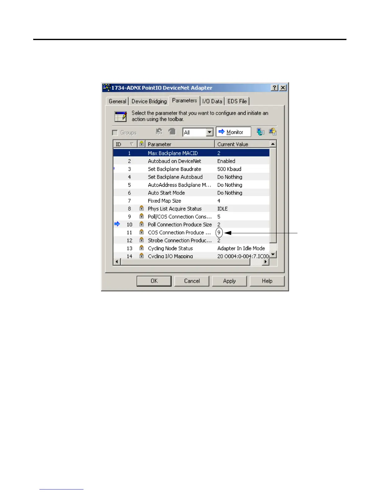
Earlier view of the parameters.
The primary network
knew you were
producing 9 bytes of
data.

 Loading...


