Publication 1734-UM002C-EN-P - July 2003
Using Auto Start Mode 3-7
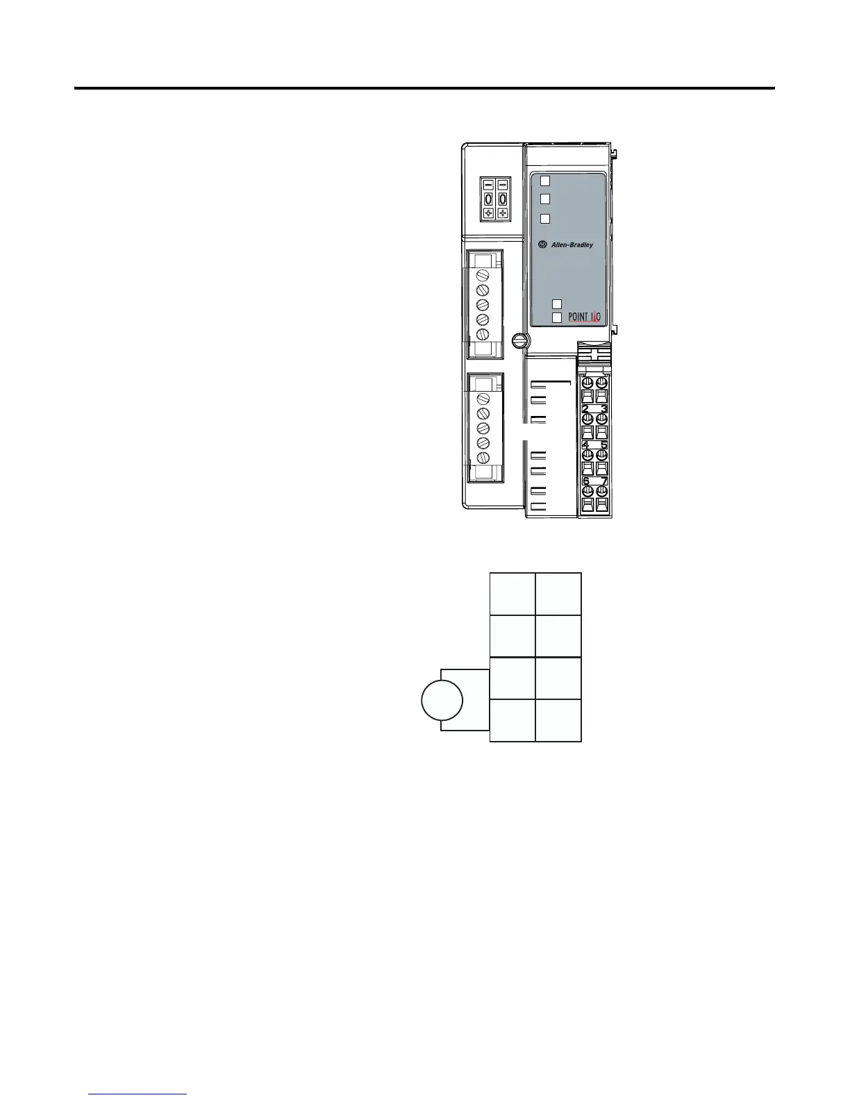
Wiring the Adapter
Your adapter’s wiring and network designations are shown below.
Adapter
Status
Network
Status
Subnet
Status
1734-ADNX
Field
Power
System
Power
CHAS GND
C
V
NC
Node Address
Thumbwheel
NC = No Connection
CHAS GND = Chassis Ground
C = Common
V = Supply
DeviceNet
Connector
C
V
NC
CHAS GND
System Power
Field Power
Adapter Status
Network Status
Subnet Status
Subnet Connector
(1734-ADNX only)
1734ADNX
NC NC
C
VV
C
V dc
This dc supply is
connected to the
internal power bus.
You cannot supply
power to the adapter
from the DeviceNet
power supply.
12/24V dc
CHAS
GND
CHAS
GND
3
5
7
01
2
4
6
NC = No Connection CHAS GND = Chassis Ground
C = Common V = Supply (Do not connect 120/240V ac power to this supply.)
42513

 Loading...


