Publication 1734-UM002C-EN-P - July 2003
Default Data Maps D-11
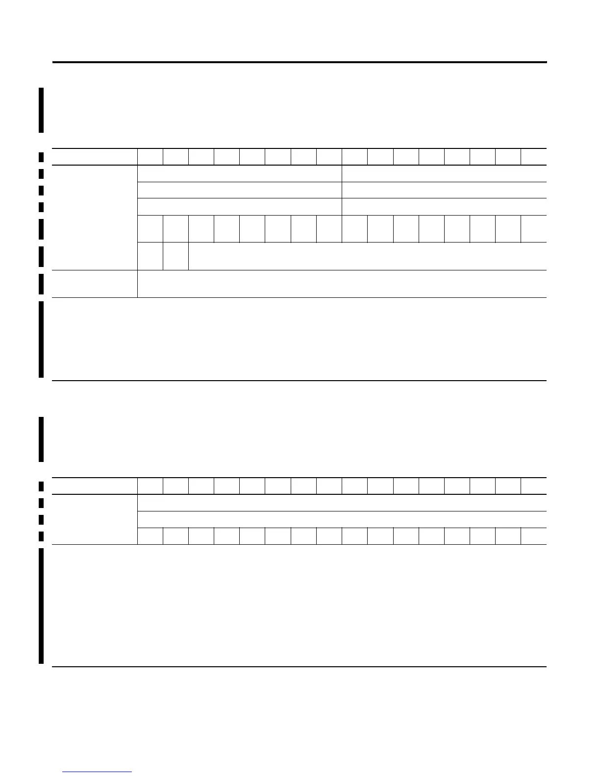
1734-IT2I Isolated Thermocouple Input Module
Message size: 8 Bytes
1734-VHSC 24V dc High Speed Counter Module
Message size: 6 Bytes
15 14 13 12 11 10 09 08 07 06 05 04 03 02 01 00
Produces (scanner Rx) Input Channel 0 - High Byte Input Channel 0 - Low Byte
Input Channel 1 - High Byte Input Channel 1 - Low Byte
Status Byte for Channel 1 Status Byte for Channel 0
OR UR HHA L
LA
HA LA CM CF OR UR HHA L
LA
HA LA CM CF
OR UR Cold Junction Temperature
(Selectable: Channel 0, Channel 1, or Average of both Channel 0 and 1)
Consumes (scanner
Tx)
No consumed data
Where: CF = Channel Fault status; 0 = no error, 1 = fault
CM = Calibration Mode; 0 = normal, 1 = calibration mode
LA = Low Alarm; 0 = no error, 1 = fault
HA = High Alarm; 0 = no error, 1 = fault
LLA = Low/Low Alarm; 0 = no error, 1 = fault
HHA = High/High Alarm; 0 = no error, 1 = fault
UR = Underrange; 0 = no error, 1 = fault
OR = Overrange; 0 = no error, 1 = fault
15 14 13 12 11 10 09 08 07 06 05 04 03 02 01 00
Produces (scanner Rx) Channel 0 value of present counter state (LSW)
Channel 0 value of present counter state (MSW)
PE EF NR 0 FS FS OS OS 0 ZS BS AS C1 C0 ZD 0
Where: PE = Programming error
EF = EEPROM fault status
NR = Not ready status bit
FS = Output fault status bit - bit 10 for output 0, bit 11 for output 1
OS = Output on/off status bit - bit 8 for output 0, bit 9 for output 1
ZS = Z input status
BS = B input status
AS = A input status
C = Stored data count
ZD = Zero frequency detected
LSW = Least significant word
MSW = Most significant word

 Loading...


