Publication 1734-UM002C-EN-P - July 2003
Using Auto Start Mode 3-9
Adding Non-Backplane
Modules to Subnet
(1734-ADNX Only)
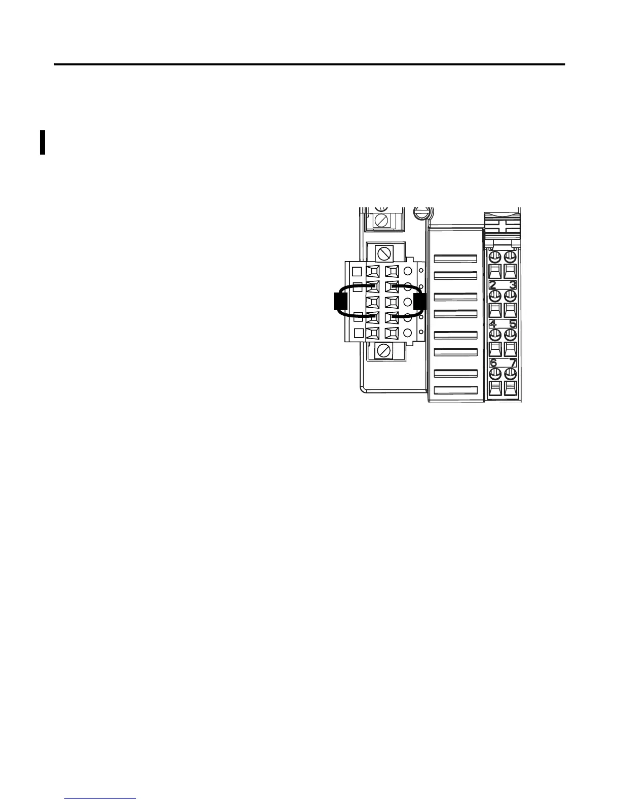
The Subnet must be properly terminated. A terminating resistor
(included with the 1734-ADNX) must be placed at each end of the
Subnet trunk segment (see the Rockwell Automation publication
DeviceNet Cable System Planning and Installation Manual, publication
no. DN-6.7.2). If no cable is attached to the 1734-ADNX Subnet
connector, two resistors should be attached across the blue CAN_H
and white CAN_L wires, as shown below.
The node addresses of all non-Backplane Subnet modules must be
numerically greater than the number of modules residing on the
1734-ADNX backplane.
Non-backplane modules should be configured to allow them to
communicate at the desired baud rate.
If a module’s configuration affects the amount of I/O data produced
or consumed by that module, the desired configuration should be
downloaded to the module before beginning the Auto Start Mode
operation.
CAN_Low (Blue)
CAN_High (White)
43506

 Loading...


