Publication 1734-UM002C-EN-P - July 2003
D-8 Default Data Maps
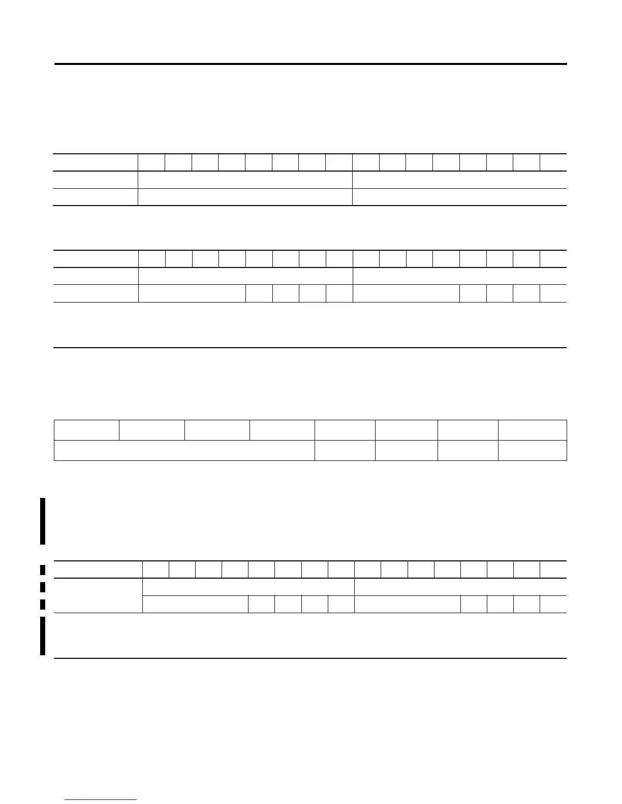
1734-OE2C Analog Current Output Module
Message size: 4 bytes
Message size: 2 Bytes
Channel Status
1734-OE2V Analog Output Module
Message size: 2 Bytes
15 14 13 12 11 10 09 08 07 06 05 04 03 02 01 00
Consumes (Tx) Output Channel 0 High Byte Output Channel 0 Low Byte
Output Channel 1 High Byte Output Channel 1 Low Byte
15 14 13 12 11 10 09 08 07 06 05 04 03 02 01 00
Produces (Rx) High Byte - Channel 1 Status Low Byte - Channel 0 Status
Not used HCA LCA CM CF Not used HCA LCA CM CF
Where:CF = Channel Fault status0 = no error1 = fault
CM = Calibration Mode0 = normal1 = calibration mode
LCA = Low Clamp Alarm0 = no error1 = fault
HCA = High Clamp Alarm0 = no error1 = fault
Table D.B
Channel Status Byte
Bit 7 Bit 6 Bit 5 Bit 4 Bit 3 Bit 2 Bit 1 Bit 0
Not used High Clamp Low Clamp CAL Mode Channel Fault
15 14 13 12 11 10 09 08 07 06 05 04 03 02 01 00
Produces (scanner Rx) Channel 1 Status - High Byte Channel 0 Status - Low Byte
Not used HCA LCA CM ST Not used HCA LCA CM ST
Where: ST = Channel Fault Status; 0 = no error, 1 = fault
CM = Calibration Mode; 0 = normal, 1 = calibration mode
LCA = Low Clamp Alarm; 0 = no error, 1 = fault
HCA = High Clamp Alarm; 0 = no error, 1 = fault

 Loading...


