110 Rockwell Automation Publication 2094-UM001J-EN-P - March 2017
Chapter 5 Connect the Kinetix 6000 Drive System
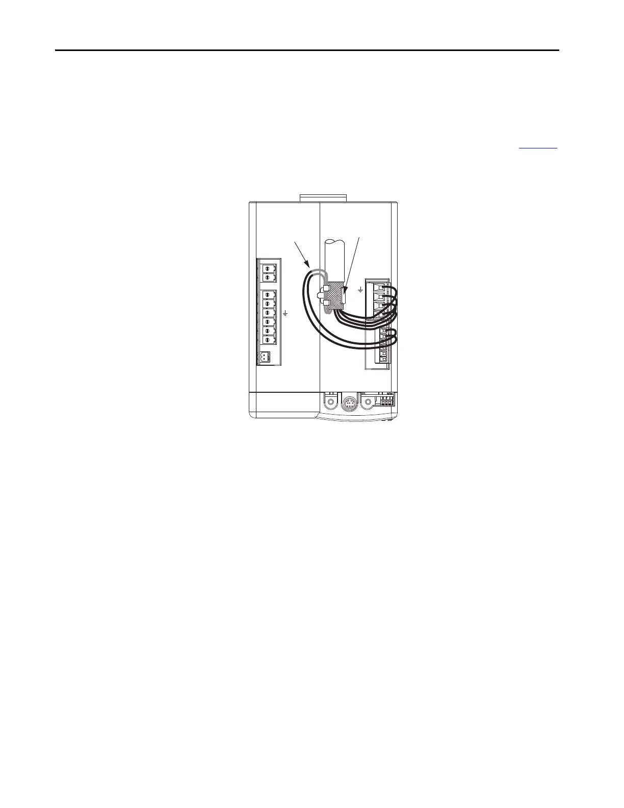
These cables contain three-phase power wires and brake wires. The brake wires
have a shield braid (shown below as gray) that folds back under the cable clamp
before the conductors are attached to the motor brake (BC) connector.
Thermal switch wires are included in the feedback cable.
Refer to Axis Module/Rotary Motor Wiring Examples beginning on page 198
for interconnect diagrams.
Figure 58 - Motor Power Terminations (cables with brake wires)
The cable shield clamp shown above is mounted to an IAM module. Cables
attach to the clamp on each AM module in the same way.
DC-
DC+
L3
L2
L1
CONT EN-
CONT EN+
CTRL 2
CTRL 1
W
V
U
MBRK -
MBRK +
COM
PWR
DBRK -
DBRK +
1 2 3 4
1 2 3 4 5 6
BAUD
RATE
TX
RX
DPI
Resistive/Motor Brake
(BC) Connector
Motor Power
(MP) Connector
Motor Cable Shield
Clamp
Kinetix 6000
IAM/AM Module
(IAM module is shown)
MP-Series Cable
Brake Wires
 Loading...


