Rockwell Automation Publication 2094-UM001J-EN-P - March 2017 111
Connect the Kinetix 6000 Drive System Chapter 5
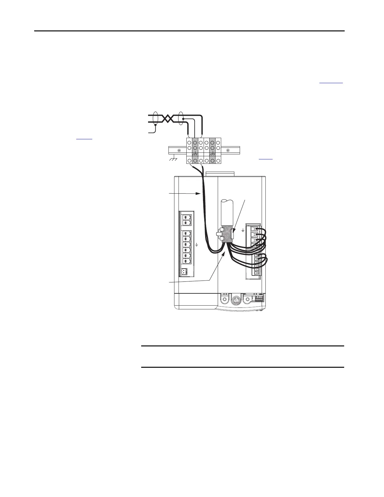
The 1326AB (resolver) power cables (catalog number 1326-CPx1T-L-xxx)
contain the three-phase wires, brake wires, and thermal switch wires. To
improve the EMC performance of your system, route the wires as shown.
Refer to Axis Module/Rotary Motor Wiring Examples beginning on page 198
for interconnect diagrams.
Figure 59 - Motor Power Terminations (1326-CPx1T-L-xxx cable)
The cable shield clamp shown above is mounted to an IAM module. Cables
attach to the clamp on each AM module in the same way.
DC-
DC+
L3
L2
L1
CONT EN-
CONT EN+
CTRL 1
CTRL 2
W
V
U
MBRK -
MBRK +
COM
PWR
DBRK -
DBRK +
1 2 3 4
1 2 3 4 5 6
BAUD
RATE
TX
RX
DPI
Thermal Switch
Wires
Keep wires separated
as much as possible.
Resistive/Motor Brake
(BC) Connector
Motor Power
(MP) Connector
Terminal Block (mounted on DIN rail)
Refer to page 35
for treatment of painted panels.
Low-profile motor feedback connector
(2090-K6CK-D15MF) pins 16, 17, and S
provide filtering for 1326-CPx1T-L-xxx cables
(refer to page 126
for an illustration).
MF-16
MF-17
MF-S
Thermal Switch Wires
Kinetix 6000 IAM/AM Module
(IAM module is shown)
Motor Cable Shield
Clamp
IMPORTANT We recommend securing the cable shield in the clamp with a tie wrap to
improve stress relief.
 Loading...


