Rockwell Automation Publication 2094-UM001J-EN-P - March 2017 279
RBM Module Interconnect Diagrams Appendix G
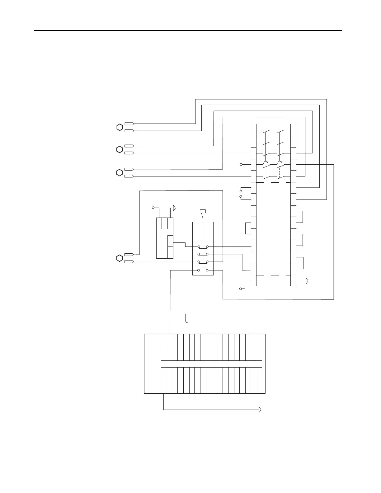
RBM Wiring Example, Category 3 Configuration per EN ISO 13849 (continued)
COM
A1 S33S52 S11 S12 S21 S22 S34 13 47 5723 37
A2 Y2X1 X2 X3 X4 Y39 Y40 Y1 14 48 5824 38
Out2 Out1 COM
PWR
COM
COM
GND-0
GND-0
GND-0
GND-0
GND-1
GND-1
GND-1
GND-1
GND-2
GND-2
GND-2
GND-2
GND-3
GND-3
GND-3
GND-3
NOT USED
NOT USED
IN-0
IN-1
IN-2
IN-3
IN-4
IN-5
IN-6
IN-7
IN-8
IN-9
IN-10
IN-11
IN-12
IN-13
IN-14
IN-15
NOT USED
NOT USED
2
4
6
8
10
12
14
16
18
20
22
24
26
28
30
32
34
36
1
3
5
7
9
11
13
15
17
19
21
23
25
27
29
31
33
35
IO_PWR
IO_PWR
IO_PWR
E-STOP *
A
B
C
D
BRKTMP0
STOPSTAT
STOPSTAT
ENABLE0
COIL0
BRKSTAT0
Reset *
* Indicates User Supplied Component
ControlLogix Input Device
1756-IB16
Light Curtain *
Safety Relay *
Allen-Bradley/Guardmaster MSR138DP
Note 5
 Loading...


