Rockwell Automation Publication 2094-UM001J-EN-P - March 2017 49
Plan the Kinetix 6000 Drive System Installation Chapter 2
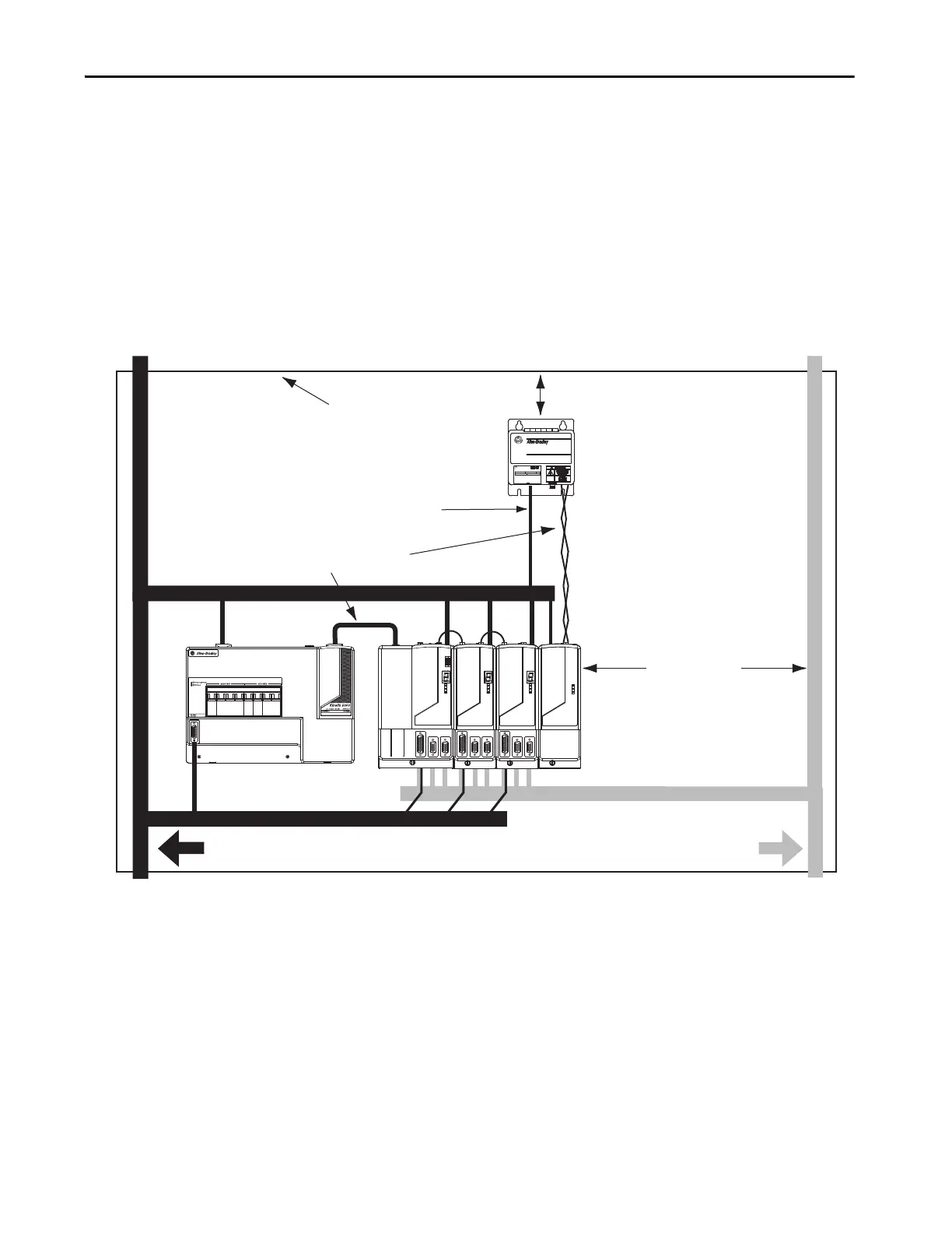
When mounting your shunt module inside the enclosure, follow these
additional guidelines:
• Mount metal-clad modules anywhere in the dirty zone, but as close to
the Bulletin 2094 drive system as possible.
• Route shunt power wires with motor power cables.
• Keep unshielded wiring as short as possible. Keep shunt wiring as flat to
the cabinet as possible.
• Separate shunt power cables from other sensitive, low voltage signal
cables.
Figure 20 - External Shunt Module Inside the Enclosure
C
D
D
D
D
D
VD
C
VD
1394 Digital Servo Controller
300W Shunt Module
BULLETIN 1394 300W SHUNT MODULE
ALLEN-BRADLEY
FOR USE WITH 1394-SJT22-X SYSTEM MODULE
CAT. PART SER.
INPUT DC INPUT AC
FOR FUSE REPLACEMENT USE:
BUSSMAN CAT. NO.
R
D
Line Interface Module
Kinetix 6000
System
Dirty Wireway
Clean Wireway
Motor Power Cables
Enclosure
2094-BSP2
Shunt Module
I/O and Feedback Cables
150 mm (6.0 in.)
clearance (min) on all four
sides of the shunt module.
Shunt thermal Switch and Fan Wires (when present)
Very Dirty Connections Segregated
(not in wireway)
Shunt Power Wiring Methods:
Twisted pair in conduit (1st choice).
Shielded twisted pair (2nd choice).
Twisted pair, two twists per foot (min) (3rd choice).
No sensitive
equipment within
150 mm (6.0 in.).
Route 24V DC I/O
shielded cable.
Route encoder/analog/registration
shielded cables.
 Loading...


