50 Rockwell Automation Publication 2094-UM001J-EN-P - March 2017
Chapter 2 Plan the Kinetix 6000 Drive System Installation
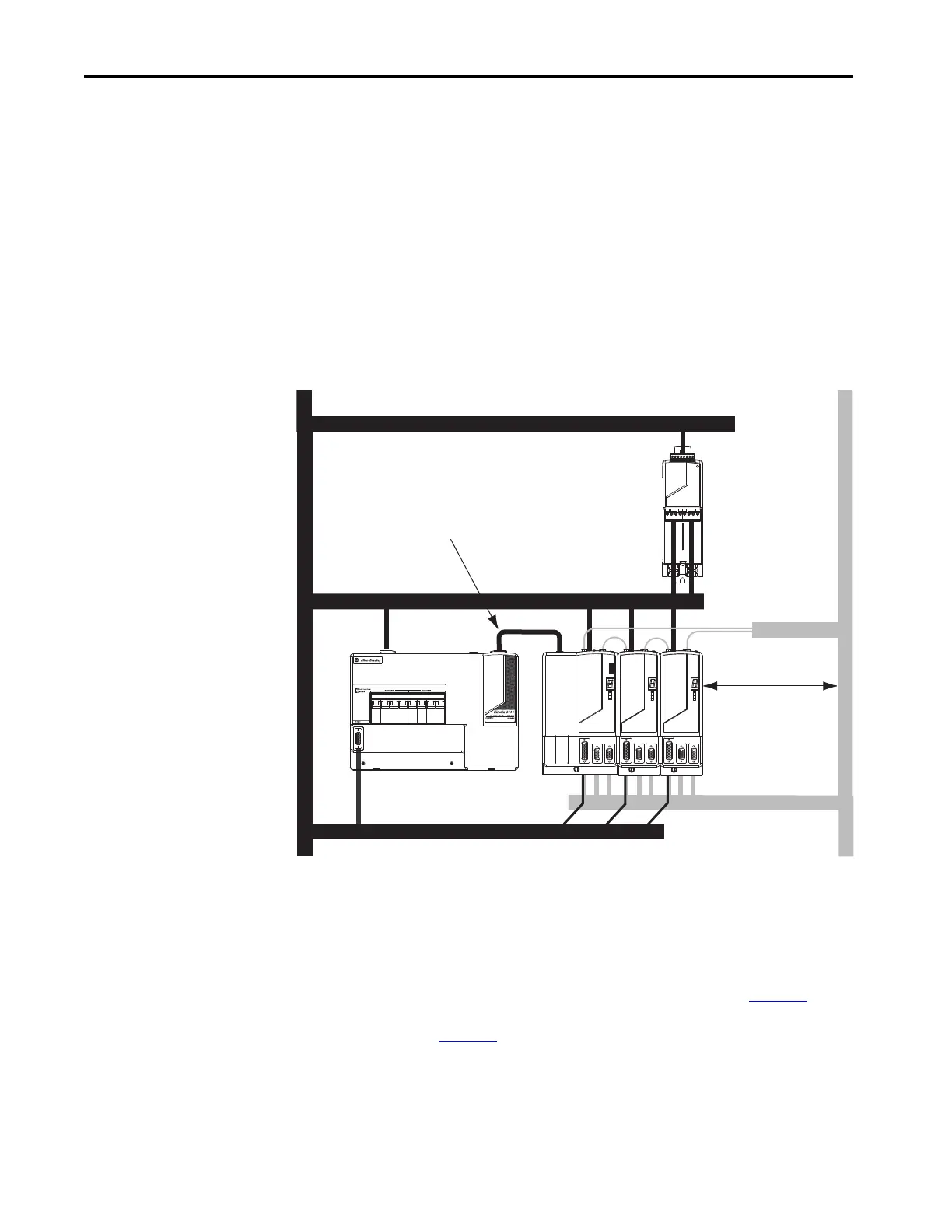
Resistive Brake Modules
Observe these guidelines when mounting your RBM module:
• Mount circuit components and wiring in the dirty zone or in an external
shielded enclosure. If mounting the RBM module in a separate
ventilated shielded enclosure, run wiring inside metal conduit to
minimize the effects of EMI and RFI.
•Keep unshielded wiring as short as possible. Keep wiring as flat to the
cabinet as possible.
• Route RBM module power and I/O cables separate from other sensitive
low voltage signal cables.
Figure 21 - Noise Zones (RBM mounted above AM module)
Motor Brake and Thermal Switch
The thermal switch and brake are mounted inside the motor, but how you
connect to the axis module depends on the motor series.
Refer to Wire the Motor/Resistive Brake (BC) Connector on page 113
for
wiring guidelines. Refer to Axis Module/Rotary Motor Wiring Examples
beginning on page 198
for the interconnect diagram of your drive/motor
combination.
Line Interface Module
Kinetix 6000
System
Dirty Wireway
Clean Wireway
Motor Power Cables
Very Dirty LIM/IAM Connections
Segregated (not in wireway)
RBM I/O
LIM VAC Input Power
IAM/AM Feedback and
(clean) I/O
LIM and IAM/AM (dirty) I/O
No sensitive
equipment within
150 mm (6.0 in.).
Fiber-optic Cable
 Loading...


