EasyManuals Logo

Allen-Bradley PLC-5 User Manual

Allen-Bradley PLC-5
388 pages
To Next Page IconTo Next Page
To Previous Page IconTo Previous Page
Page #366 background imageLoading...
Page #366 background image
Publication 1785-UM012D-EN-P - July 2005
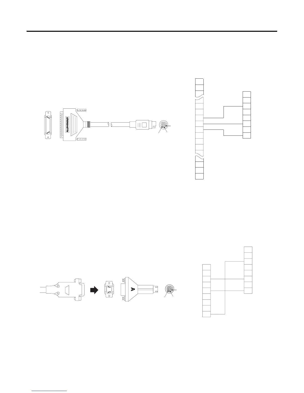
G-6 Cable Reference
Cable - 1784-CP6
Connects Workstation Using 1784-KT, -KT/2, -KL, or -KL/B
to Controller
Cable and Adapter - 1784-CP7 Connects to Controller via 9-pin D-Shell of a 1784-CP,
-CP5, or -PCM5 cable
A
38
37
36
35
34
33
32
31
7
6
5
2
3
1
3
2
1
61
62
8
4
Shield
Blue
Shield
Blue
Clear
18378
8-Pin Mini-DIN
Pin 1
Pin 3
Pin 6
43
21
1
62
22
62-Pin D-Shell
Workstation
62-Pin D-Shell
Workstation
Controller
Controller
Clear
9
8
7
6
5
4
3
7
6
5
2
3
1
8
4
Shield
BlueBlue
Clear
Clear
2
1
18377
8-Pin Mini-DIN
9-Pin D-Shell
1
5
6
9
8-Pin Mini-DIN
Pin 1
Pin 3
Pin 6
Controller
Controller
9-Pin D-Shell
Shield

Table of Contents

Other manuals for Allen-Bradley PLC-5

Questions and Answers:

Question and Answer IconNeed help?

Do you have a question about the Allen-Bradley PLC-5 and is the answer not in the manual?

Allen-Bradley PLC-5 Specifications

General IconGeneral
Programming SoftwareRSLogix 5
Programming LanguagesLadder Logic
Power Supply120/240V AC or 24V DC
Communication PortsDH+, Remote I/O, Ethernet/IP, ControlNet
Operating Temperature0 to 60°C (32 to 140°F)
Relative Humidity5 to 95% non-condensing
MemoryUp to 64K words (user program and data)

Related product manuals