Publication 1747-RM001G-EN-P - November 2008
Processor Files 1-9
Assign control addresses as follows.
DN = Done
EM = Stack Empty
ER = Error
UL = Unload
IN = Inhibit
FD = Found
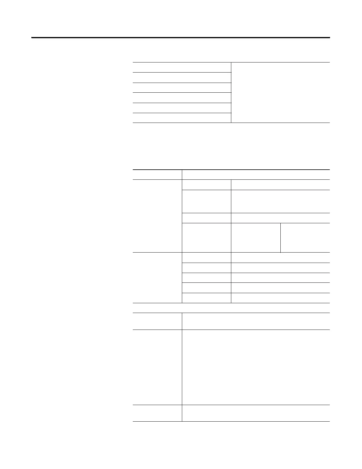
Table 1.12 Control File Addressing Format
Format Explanation
Rf:e
R Control file
f File number. Number 6 is the default file. A
file number between 9 and 255 can be used
if additional storage is required.
: Element delimiter
e Element number Ranges from 0 to
255. These are
3-word elements.
See figure above.
Rf:e.s/b Rf:e Explained above.
. Word delimiter
s Indicates word
/ Bit delimiter
b Bit
Examples:
R6:2 Element 2, control file 6
Address bits and words by using the format Rf:e.s/b
R6:2/15 or R6:2/EN
R6:2/14 or R6:2/EU
R6:2/13 or R6:2/DN
R6:2/12 or R6:2/EM
R6:2/11 or R6:2/ER
R6:2/10 or R6:2/UL
R6:2/9 or R6:2/IN
R6:2/8 or R6:2/FD
R6:2.1 or R6:2.LEN
R6:2.2 or R6:2.POS
Enable bit
Unload Enable bit
Done bit
Stack Empty bit
Error bit
Unload bit
Inhibit bit
Found bit
Length value
Position value
R6:2.1/0
R6:2.2/0
Bit 0 of length value
Bit 0 of position value
Table 1.11 Control Elements

 Loading...


