Publication 1747-RM001G-EN-P - November 2008
E-24 Data File Organization and Addressing
Capturing M0-M1 File Data
The first two ladder diagrams in the last section illustrate a technique allowing
you to capture and use M0 or M1 data as it exists at a particular time. In the
first figure, bit M0:2.1/1 could change state between rungs 1 and 2. This could
interfere with the logic applied in rung 2. The second figure avoids the
problem. If rung 1 is true, bit B3/10 captures this information and places it in
rung 2.
In the second example of the last section, a COP instruction is used to
monitor the contents of an M1 file. When the instruction goes true, the 6
words of data in file #M1:4.3 is captured as it exists at that time and placed in
file #N10.0.
Specialty I/O Modules with Retentive Memory
Certain specialty I/O modules retain the status of M0-M1 data after power is
removed. See your specialty I/O module user’s manual. This means that an
OTE instruction having an M0 or M1 address remains on if it is on when
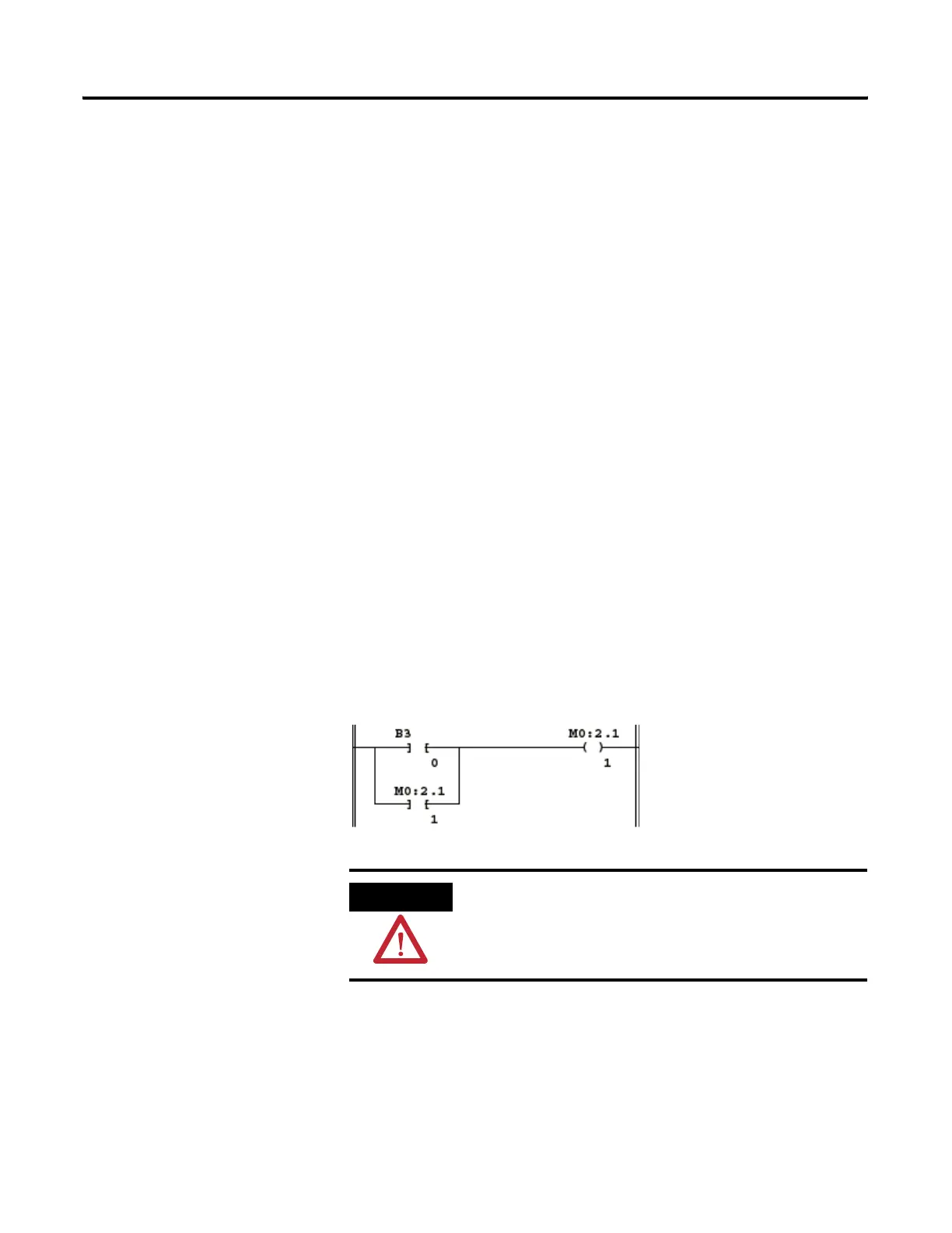
power is removed. A “hold-in” rung as shown below will not function as it
would if the OTE instruction were non-retentive on power loss. If the rung is
true at the time power is removed, the OTE instruction latches instead of
dropping out; when power is again applied, the rung is evaluated as true
instead of false.
You can achieve non-retentive operation by unlatching the retentive output
with the first pass bit at powerup.
ATTENTION
When used with a specialty I/O module having
retentive outputs, this rung can cause unexpected
start-up on powerup.

 Loading...


