140 Rockwell Automation Publication 1783-UM007G-EN-P - February 2017
Chapter 5 Install Stratix 5700 Switches
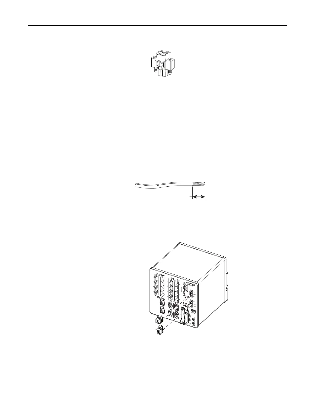
1. Locate the power connector.
2. Identify the positive and return DC power connections.
The positive DC power connection is labeled DC+, and the negative
DC power connection is the adjacent connection labeled DC-.
3. Measure a length of 0.82…0.52 mm
2
(18…20 AWG) copper wire long
enough to connect to the DC power source.
4. Use an 18-gauge wire-stripping tool to strip each of the two wires to
6.3 mm (0.25 in.) ± 0.5 mm (0.02 in.).
Do not strip more than 6.8 mm (0.27 in.) of insulation from the wire.
Stripping more than the recommended amount of wire can leave wire
exposed after installation.
5. Loosen the two captive screws that attach the power connector to the
switch, and remove the power connector.
Remove both connectors if you are connecting to two power sources.
6. Insert the exposed part of the positive wire into the connection labeled
DC+ and the exposed part of the return wire into the connection
labeled DC-.
32280-M
6.3 mm (0.25 in.) ± 0.5 mm (0.02 in.)
31789-M
32278-M

 Loading...


