Rockwell Automation Publication 1783-UM007G-EN-P - February 2017 533
Cables and Connectors Appendix D
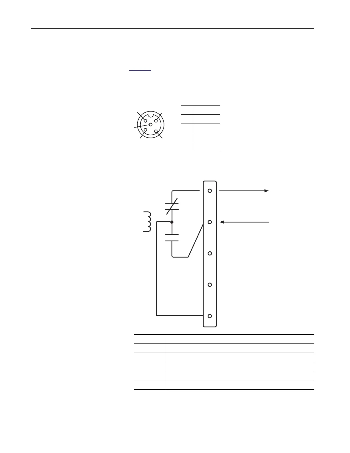
Alarm Ports
Alarm ports are included only on ArmorStratix 5700 switches with PoE.
Figure 85 shows the front-panel alarm relay connector and ports. The alarm
connector uses a male 5-pin DC Micro-style (M12) connector configuration
cordset, such as Allen-Bradley Bulletin 889D.
Figure 85 - Alarm Connector Pinout
Figure 86 - Wiring Example for Alarm Inputs and Outputs
4
5
3
1
2
1NO
2NC
3 Unconnected
4 Unconnected
5 Common
Alarm
Relay
Coil
1
2
3
4
5
+24V DC from User
To Alarm Input
Alarms Connector
NO
COM
NC
Label Connection
NO Alarm Output Normally Open (NO) connection
NC Alarm Output Normally Closed (NC) connection
Unconnected Unconnected
Unconnected Unconnected
COM Alarm Output Common connection

 Loading...


