Rockwell Automation Publication 1783-UM007G-EN-P - February 2017 139
Install Stratix 5700 Switches Chapter 5
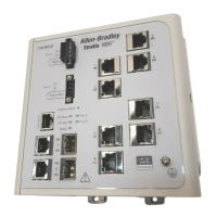
5. Insert the ground screw into the functional ground screw opening on
the front panel.
6. Use a ratcheting torque screwdriver to tighten the ground screws and
ring terminal lugs to the switch front panel to 0.4 N
m (3.5 lbin).
Do not exceed the recommended torque.
7. Attach the other end of the ground wire to a grounded bare metal
surface, such as a ground bus, a grounded DIN rail, or a grounded bare
rack.
Wire the Switch
DC Power Source
To wire the DC power source for the switch, follow these steps.
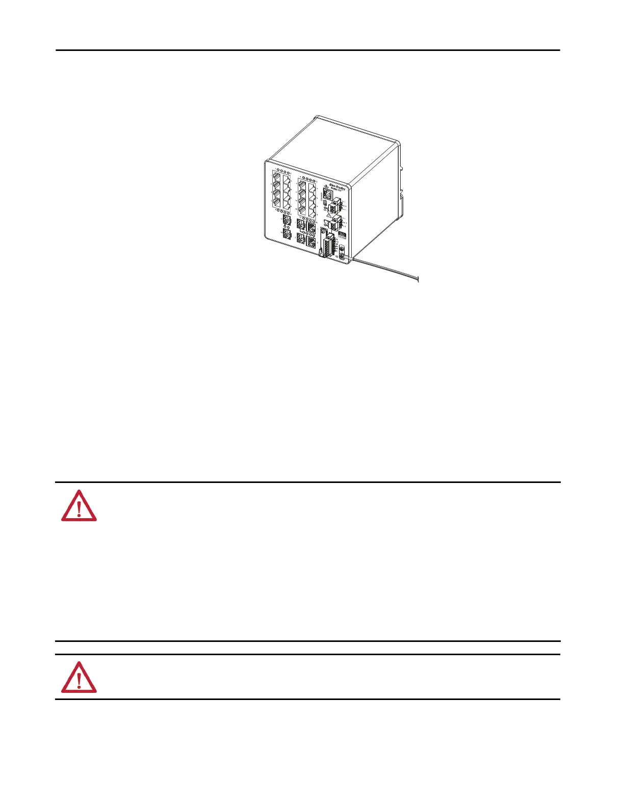
32276-M
Ring Terminal Lug (single lug shown)
ATTENTION: Before performing any of the following procedures, make sure that power is removed from the DC circuit or the
area is nonhazardous before proceeding:
• This product is intended to be supplied by a Class 2 power source marked with ‘Class 2’ and rated from 12, 24, or 48V DC, 2.5 A.
• To comply with the CE Low Voltage Directive (LVD), this equipment must be powered from a source compliant with the safety
extra low voltage (SELV) or protected extra low voltage (PELV).
• A readily accessible two-poled disconnect device must be incorporated in the fixed wiring.
• This product relies on the building’s installation for short-circuit (overcurrent) protection. Make sure that the protective device is
rated not greater than 3 A.
• Installation of the equipment must comply with local and national electrical codes.
• Allow only trained and qualified personnel to install, replace, or service this equipment.
ATTENTION: For wire connections to the power and relay connector, you must use UL- and CSA-rated, style 1007 or 1569
twisted-pair copper appliance wiring material (AWM) wire.
 Loading...