Rockwell Automation Publication 1783-UM007G-EN-P - February 2017 83
Install Stratix 5400 Switches Chapter 3
Wire the Switch
DC Power Source
For switches with Power over Ethernet (PoE) capability, PoE power is drawn
from the single power connection. There is no separate power input for PoE.
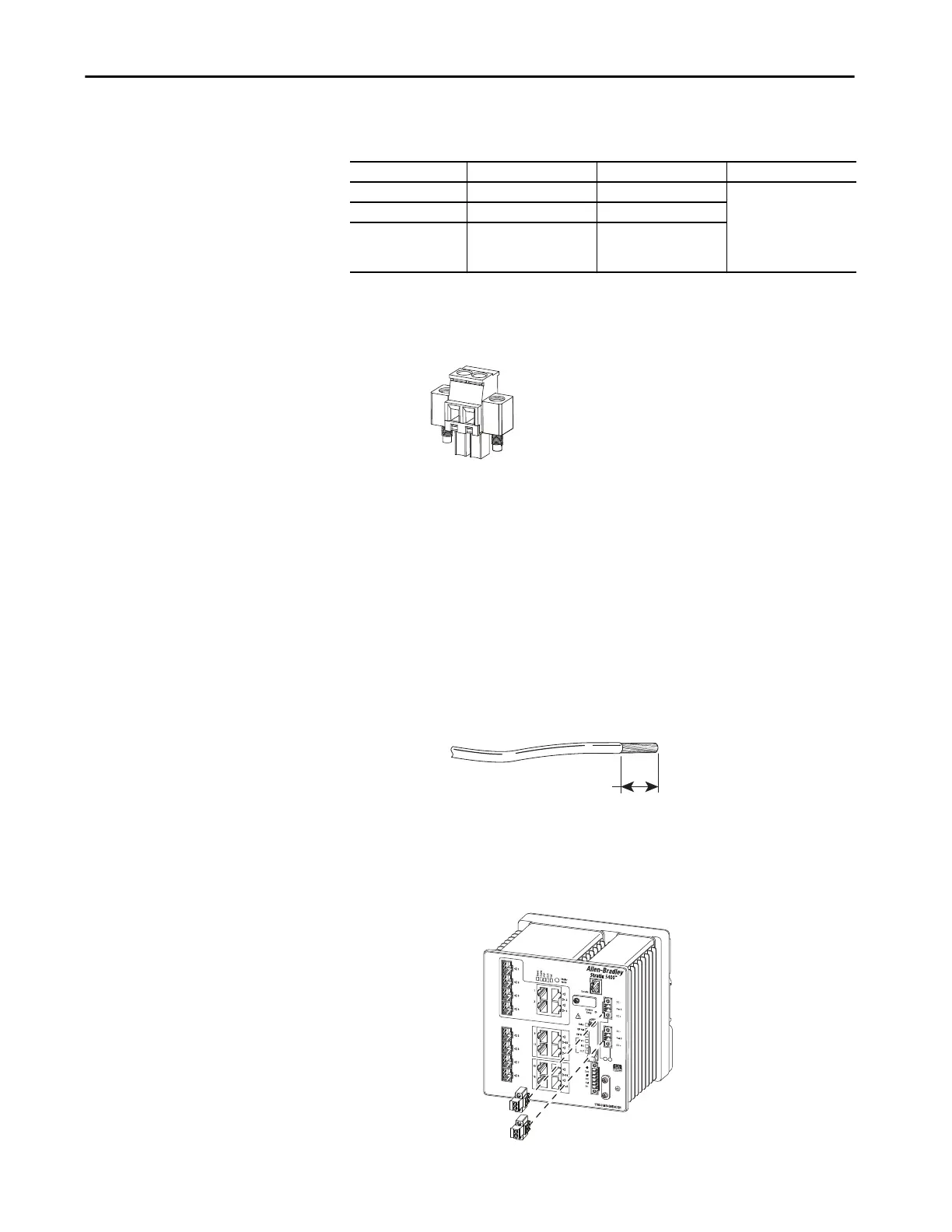
To wire the DC power source for the switch, follow these steps.
1. Locate the power connector.
2. Identify the positive and return DC power connections.
The positive DC power connection is labeled DC+, and the negative
DC power connection is the adjacent connection labeled DC-.
3. Measure a length of 0.82…0.52 mm
2
(18…20 AWG) copper wire long
enough to connect to the DC power source.
4. Use an 18-gauge wire-stripping tool to strip each of the two wires to
6.3 mm (0.25 in.) ± 0.5 mm (0.02 in.).
Do not strip more than 6.8 mm (0.27 in.) of insulation from the wire.
Stripping more than the recommended amount of wire can leave wire
exposed after installation.
5. Loosen the two captive screws that attach the power connector to the
switch, and remove the power connector.
Remove both connectors if you are connecting to two power sources.
Switch Configuration Required Voltage Input Power Supplied per Port Allen-Bradley Products
PoE 44-54V 15.4 W, max Switched-mode power
supplies:
• 1606-XL Standard
• 1606-XLE Essential
• 1606-XLP Compact
• 1606-XLS Performance
PoE+ 50-54V 30 W, max
Non-PoE 12…54V Not applicable
6.3 mm (0.25 in.) ± 0.5 mm (0.02 in.)
31789-M
32558-M

 Loading...


