Rockwell Automation Publication 1783-UM007G-EN-P - February 2017 179
Install Stratix 8000 and 8300 Switches Chapter 6
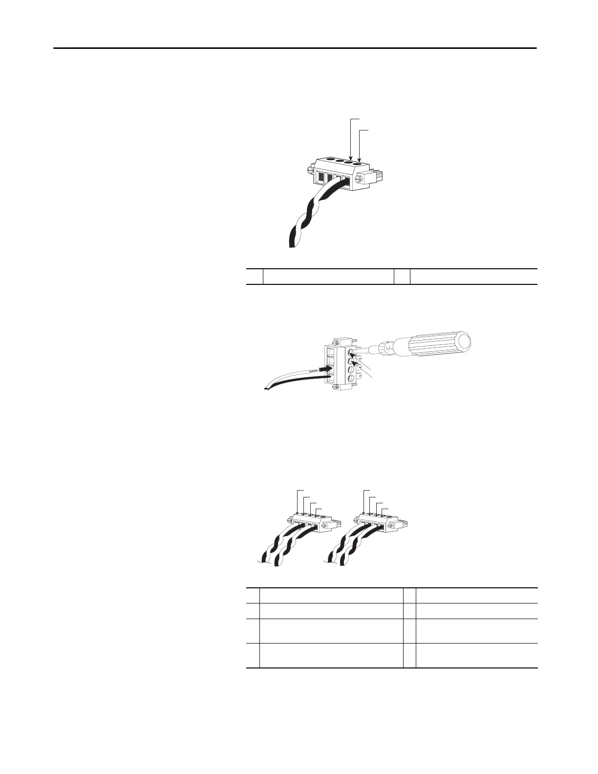
3. Insert the exposed wires for the external alarm device into the two
connections labeled A, as shown in the following figure.
4. Use a screwdriver to torque the power and relay connector captive screw
(above the installed wire leads) to 0.23 N•m (2.0 lb•in).
5. Repeat these steps to insert the input and output wires of an additional
external alarm device into the second power and relay connector.
The following figure shows the completed wiring for two power supplies
and two external alarm devices.
1 External device, relay wire A connection 1 2 External device, relay wire A connection 2
1 Power source A positive connection 5 Power source B positive connection
2 Power source A return connection 6 Power source B return connection
3 External device 1, relay wire major alarm
connection
7 External device 2, relay wire minor alarm
connection
4 External device 1, relay wire major alarm
connection
8 External device 2, relay wire minor alarm
connection
-
24
!
6
!
1
2
VRTA A
31785-M
V
RT
-
24
!
6
!
24
!
6
!
1
2
3
4
5
6
7
8

 Loading...


