86 Rockwell Automation Publication 1783-UM007G-EN-P - February 2017
Chapter 3 Install Stratix 5400 Switches
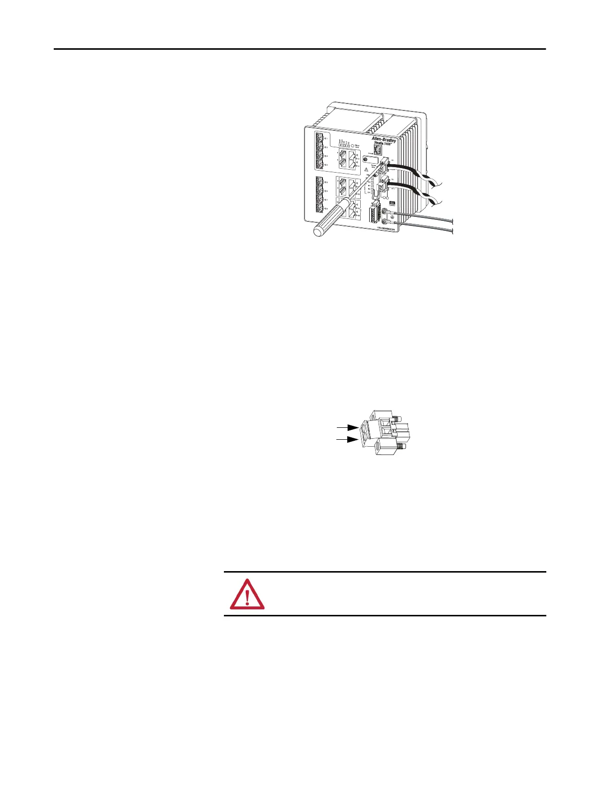
2. Use a ratcheting torque flathead screwdriver to tighten the captive
screws on the sides of the power connectors.
When you test the switch, one power source is sufficient. If you install
the switch and use a second power source, repeat this procedure for the
second power connector (Pwr B), which installs just below the primary
power connector (Pwr A).
3. When you install the switch, secure the wires from the power connectors
to the rack by using tie wraps.
4. Insert the exposed part of the positive wire into the DC+ connection
and the exposed part of the return wire into the DC- connection.
Make sure that you cannot see any wire lead. Only wire with insulation
can extend from the connector.
5. Use a ratcheting-torque screwdriver to torque the captive screws of the
power connector to 0.56 N•m (5.0 lb•in).
6. Connect the other end of the positive wire (the one connected to DC+)
to the positive terminal on the DC power source.
7. Connect the other end of the return wire (the one connected to DC-) to
the return terminal on the DC power source.
ATTENTION: If multiple power sources are used, do not exceed the specified
isolation voltage.
32514-M
DC-
DC+

 Loading...


