Rockwell Automation Publication 1783-UM007G-EN-P - February 2017 91
Install Stratix 5400 Switches Chapter 3
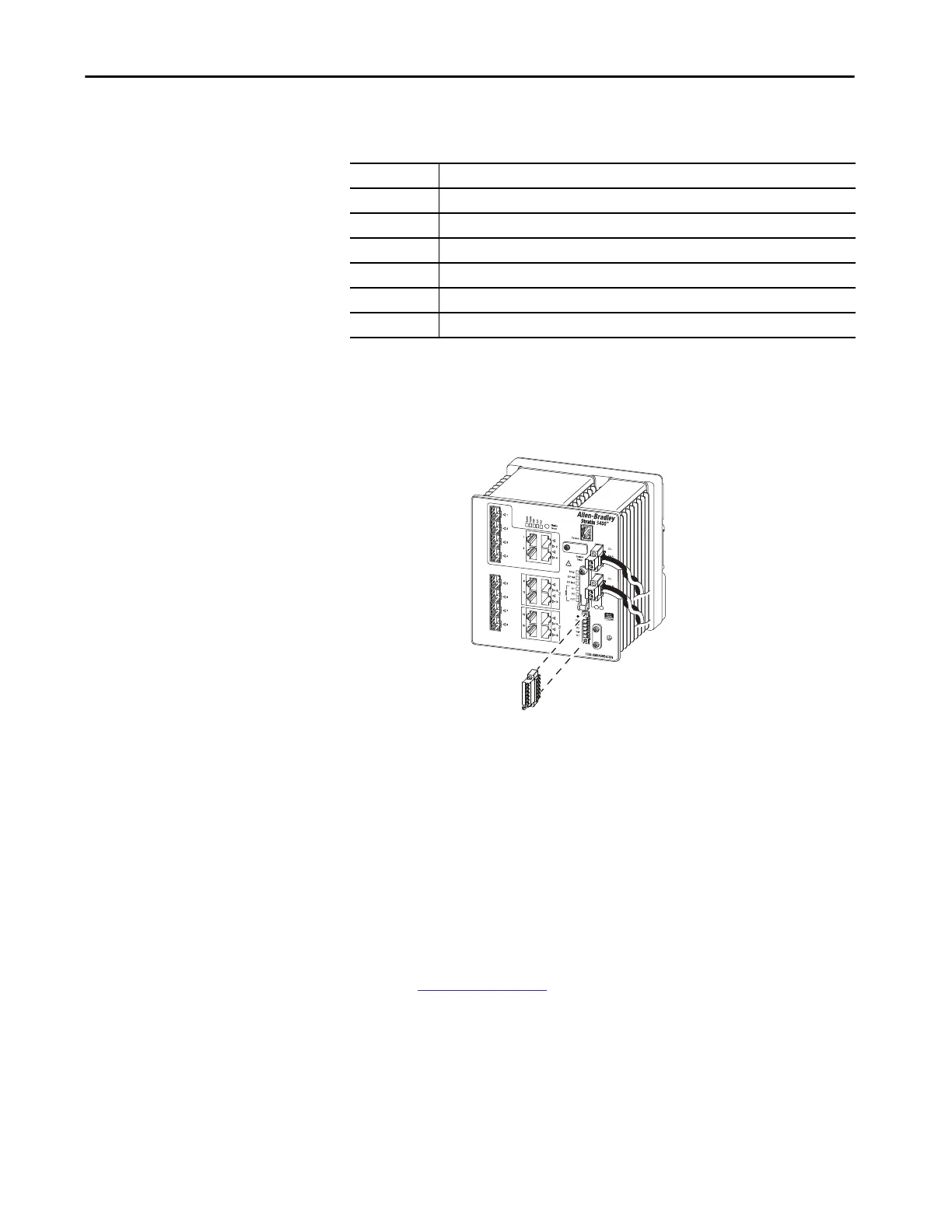
The labels for the alarm relay connector are on the switch panel.
To wire the switch to an external alarm device, follow these steps.
1. Loosen the captive screws that hold the alarm relay connector on the
switch, and remove the connector from the switch chassis.
2. Measure two strands of twisted-pair wire (18…20 AWG) long enough to
connect to the external alarm device.
Choose between creating an external alarm input or output circuit.
3. Use a wire stripper to remove the casing from both ends of each wire to
6.3 mm (0.25 in.) ± 0.5 mm (0.02 in.).
Do not strip more than 6.8 mm (0.27 in.) of insulation from the wires.
Stripping more than the recommended amount of wire can leave
exposed wire from the alarm relay connector after installation.
4. Insert the exposed wires for the external alarm device into the
connections that are based on an alarm input or output circuit setup.
See
Table 24 on page 91.
Table 24 - Alarm Relay Connector Labels
Label Connection
NO Alarm Output Normally Open (NO) connection
COM Alarm Output Common connection
NC Alarm Output Normally Closed (NC) connection
IN2 Alarm Input 2
REF Alarm Input Reference Ground connection
IN1 Alarm Input 1
32562-M
 Loading...