3-12 | Thermox WDG-V / VC / VCM with Blow Back
330.20
481.47
18.96
4.79
121.56
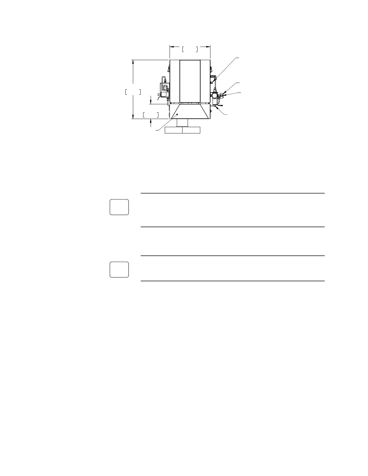
(2) 1/2” (12.7mm) conduit entries
One supplied with plug
Electronics Section
Drain Valve
Calibration Gas Inlet
1/4” compression tting
Plug during normal operations.
when calibrating shut o
aspirator air
Blow Back Regulator
Set to 80-90 PSI
Instrument Air Inlet
1/4” compression tting
Minimum 80 PSI for blow back
Figure 3-13. Sensor Inlet Connections (Floor Mount).
Manual Calibration and Aspirator Air Connections
If you have a remote calibration unit (RCU), skip the remainder of
this section and proceed to the “RCU Mechanical Installation” sec-
tion.
Aspirator air connection
If you have an AMEVision Display User Interface, you can use the
flow gauge to set the flow as described in Chapter 5.
• Connect aspirator air to the aspirator air inlet on the sensor (see Figure
3-8). The recommended initial aspirator pressure setting is 6 psi. This
will vary depending on the pressure/vacuum of the process for which
the WDG-V is installed. If you purchased an AMEVision Display User
Interface, you can use the Flow Sensor output diagnostic screen to set
the flow to the ideal rate. If you do not have an AMEVision Display
User Interface, it is recommended to adjust the aspirator until you get
a response from the analyzer, then increase the pressure by 0.25 to 0.5
psi. Do not turn on the aspirator until the sensor has been turned on
and is hot (preferably 24 hours from a cold start; 1 hour after a restart).
See page 5-1 for further detail.
• The blow back pressure regulator should be set to 80 psi.
 Loading...


