3-10 | Thermox WDG-V / VC / VCM with Blow Back
Flange Sensor Mounting Method
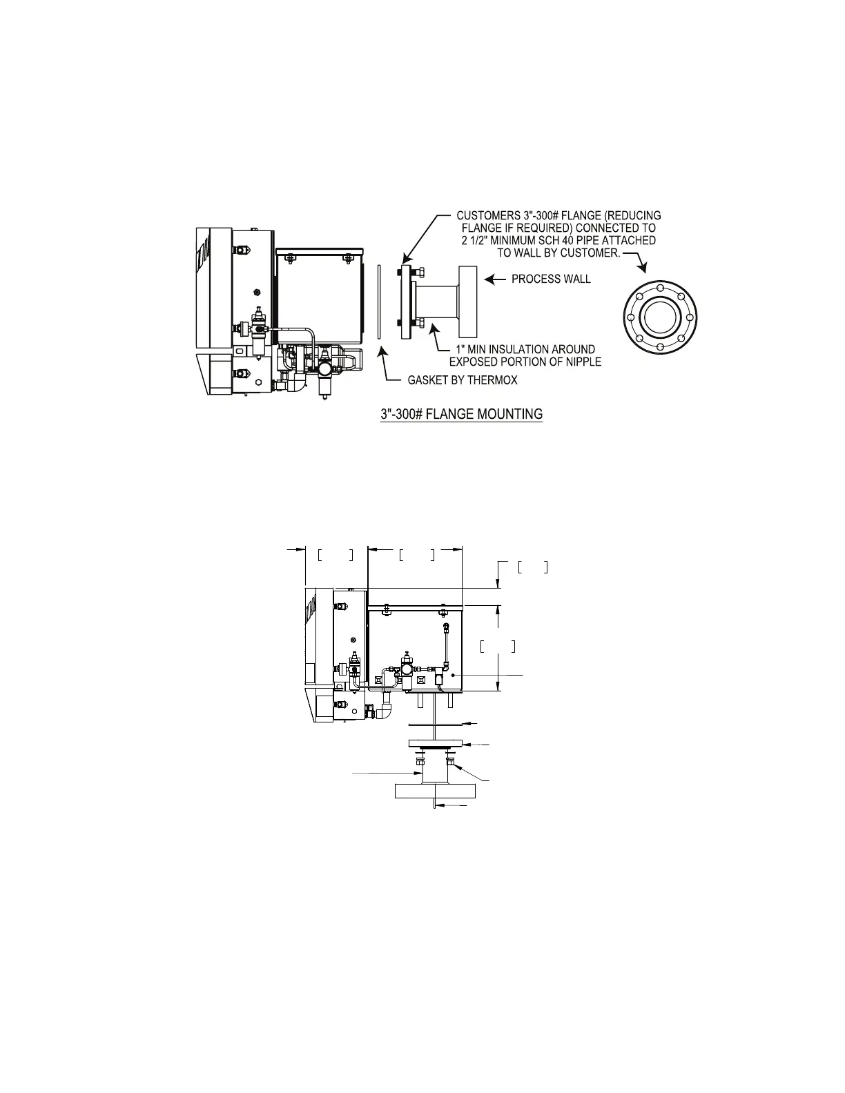
You can also mount the sensor to a 3” x 300# customer-supplied flange. In
this case, you will not need the AMETEK-supplied mounting plate with
attached protective pipe nipple. If you have a different type of flange,
AMETEK supplies a number of flange adapters.
Figure3-10.WDG-Vsensor-angemount.
Sensor Mounting (Floor Mount)
GASKET SUPPLIED BY THERMOX
13.30
337.82
2.43
61.62
8.83
224.16
12.11
307.67
Minimum 1” (25.4mm)
insulation-exposed
portion of nipple
3”-150# ange and nipple
supplied and attached
to duct by customer
Hardware supplied
by AMETEK
Sample Probe
Blow Back box
Figure3-11.WDG-Vsensor-oormount.
Mount the sensor to a 3”x 150# customer-supplied flange. You will not
need the AMETEK-supplied mounting plate with attached protective pipe
nipple. If you have a different type of flange, AMETEK supplies a variety
of flange adapters.
 Loading...


