2.6. Actuators and dashboard instruments
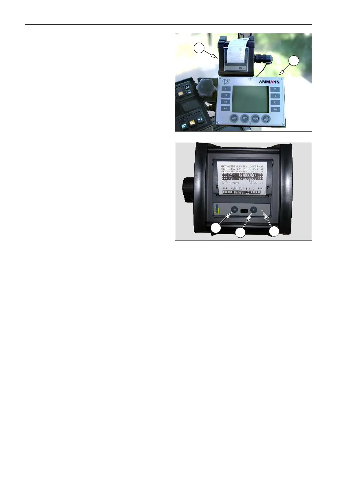
1 ACE control panel - Manual for the setting and check-
ing of the functions of the system of the ACE drum is
supplied if the roller is equipped with such system.
2 Printer
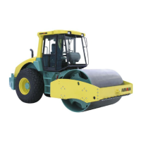
1 Printer switch on button – the button is not used (the
printer is permanently on with the ACE system)
2 Button for paper feed LF
3 Indication diode
Diode 3 indicates the condition of the equipment after swit- •
ching on the ignition box key.
A short green ashing (3 times shortly and pause) signalises
•
the readiness of the printer and its error-free state.
A longer red ashing (long ashing and pause) signalises
•
one of error conditions:
End of paper
Low operating temperature
High operating temperature
Supply voltage outside tolerance
The precise code of the error is transferred through the in-
•
terface to the control system /see the technical documen-
tation/.
The inserting of paper is described in the section Mainte-
•
nance as needed, Printer paper replacement.