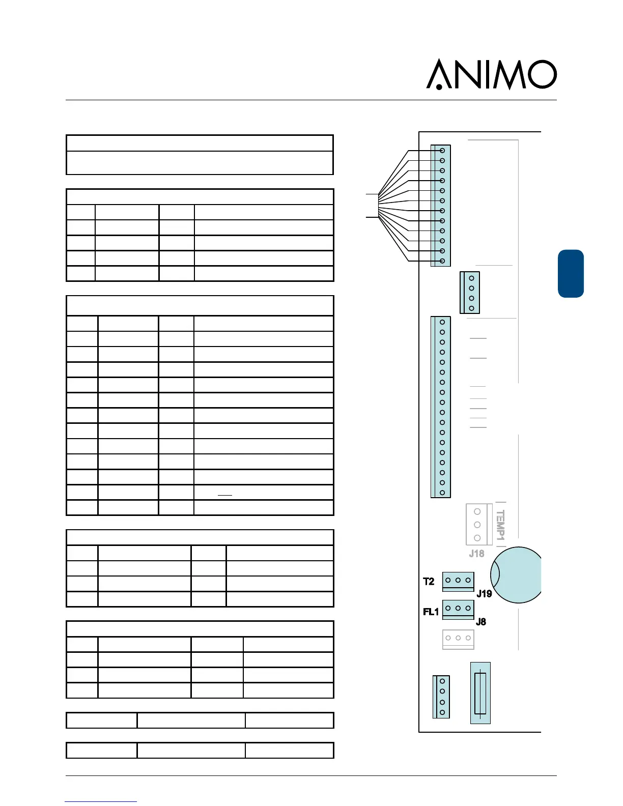
9.1.1 Main circuit board inputs
Connector J12
Connecting cable between the main circuit board and the door circuit
board
Connector J250 (PWM fan)
Pin Fan Colour Notes
1 PWM signal black
2 -
3 pos red
4 neg blue
Connector J7 (Inputs)
Pin Sensor Colour Notes
1-2 - -
3 LB Drip tray Yellow
4 GND Drip tray Black
5-8 - -
9 AS waste bin Pink Waste bin in position; contact closed
10 - -
11 DS Door 1 Orange Door closed; contact closed
12-13 - -
14 IN1 Brewer 1 Blue Brewer in ll position; contact ‘open’
15 IN2 Brewer 2 Grey Brewer in ll position; contact ‘open’
16 IN3 Door 2 Pink
Door lock locked; contact closed
17-18 - -
Connector J19 / T2 ( NTC sensor)
Pin Sensor Colour Notes
1 NTC sensor Violet
2 - -
3 NTC sensor Violet
Connector J8 / FL1 (Flow meter)
Pin Sensor Colour Notes
1 Pulse brown
2 Ground earth shield
3 Pluse white
Battery B1
Lithium 3V Type CR2032 art.no. 02816
Fuse F3
6.3 A slow blow art.no. 03391
 Loading...