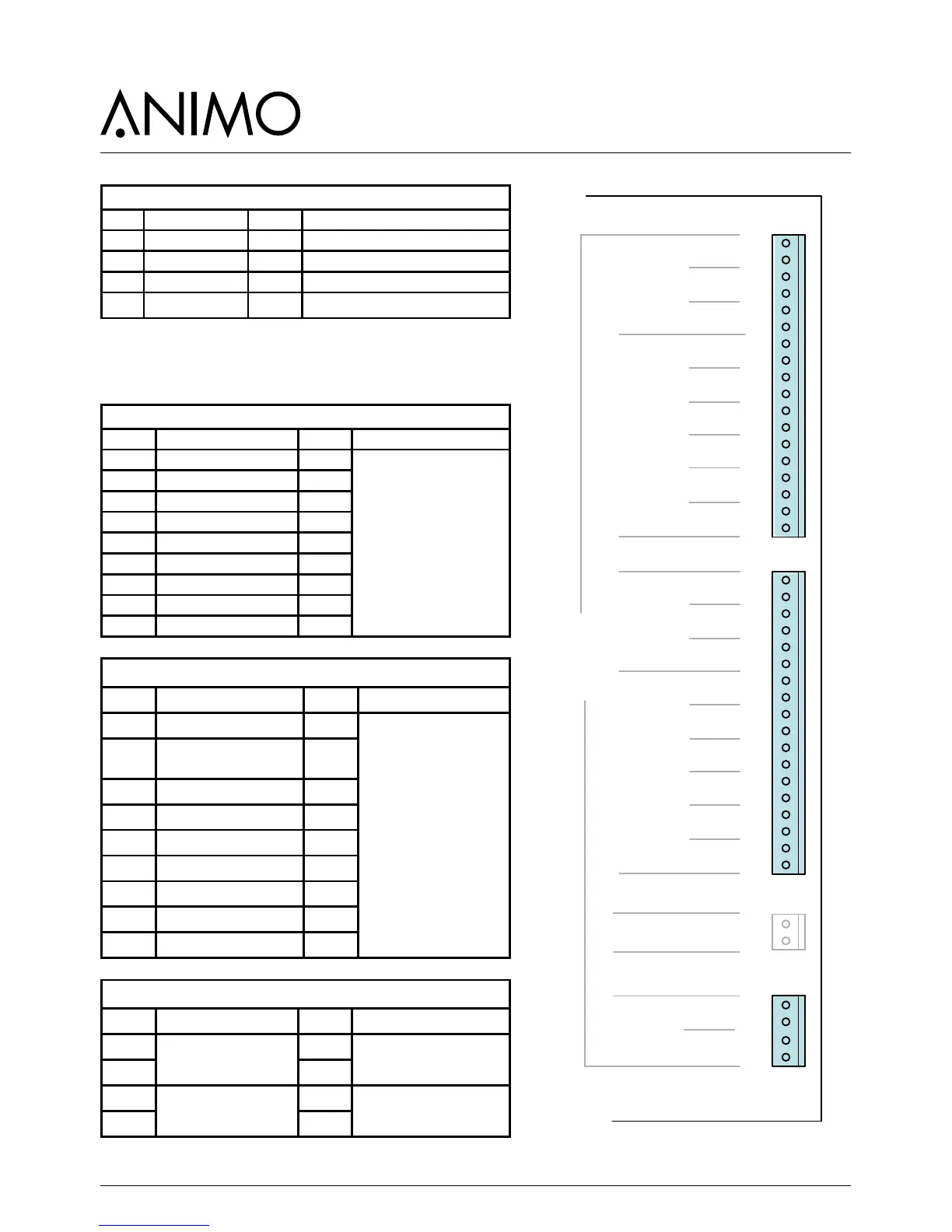
Connector J1 (Supply)
Pin Colour Notes
1 Ground (GND) black
2 Ground (GND) black
3 +24 Vdc red
4 +24 Vdc red
9.1.2 Main circuit board outputs
Connector J2
Pin Motor Colour Notes
17-18 Brewer Black
Pay attention to the right
direction!
Common +24 Vdc (red
wire) to red point on Bre-
wer, Mixer and Ingredient
motor.
15-16 Mixer 2 Violet
13-14 - -
11-12 Grinder signal 1 Brown
9-10 - -
7-8 Ingredient Motor 3 White
5-6 Ingredient Motor 4 Yellow
3-4 - -
1-2 - -
Connector J4
Pin Valve Colour Notes
17-18 KW 1 (inlet valve) Violet
Red wire is common
+24 Vdc connection
15-16 KW 2
(pump via solid state)
Rose
13-14 KW 3 (optional) Blue
11-12 DV 1 (brewer valve) Brown
9-10 DV 2 (mixer 2 valve) White
7-8 - -
5-6 DV 4 (hot water drain) Green
3-4 DV 5 Grey
1-2 DV 6 (NO valve) Orange
Connector J6
Pin Relay Colour Notes
4
-
-
3 -
2
H2 /H3 Element
via solid state relay
Red
1 White