Quick Start Guide 2-11 Test Panel Connectors
MS20xxC UG PN: 10580-00305 Rev. J 2-21
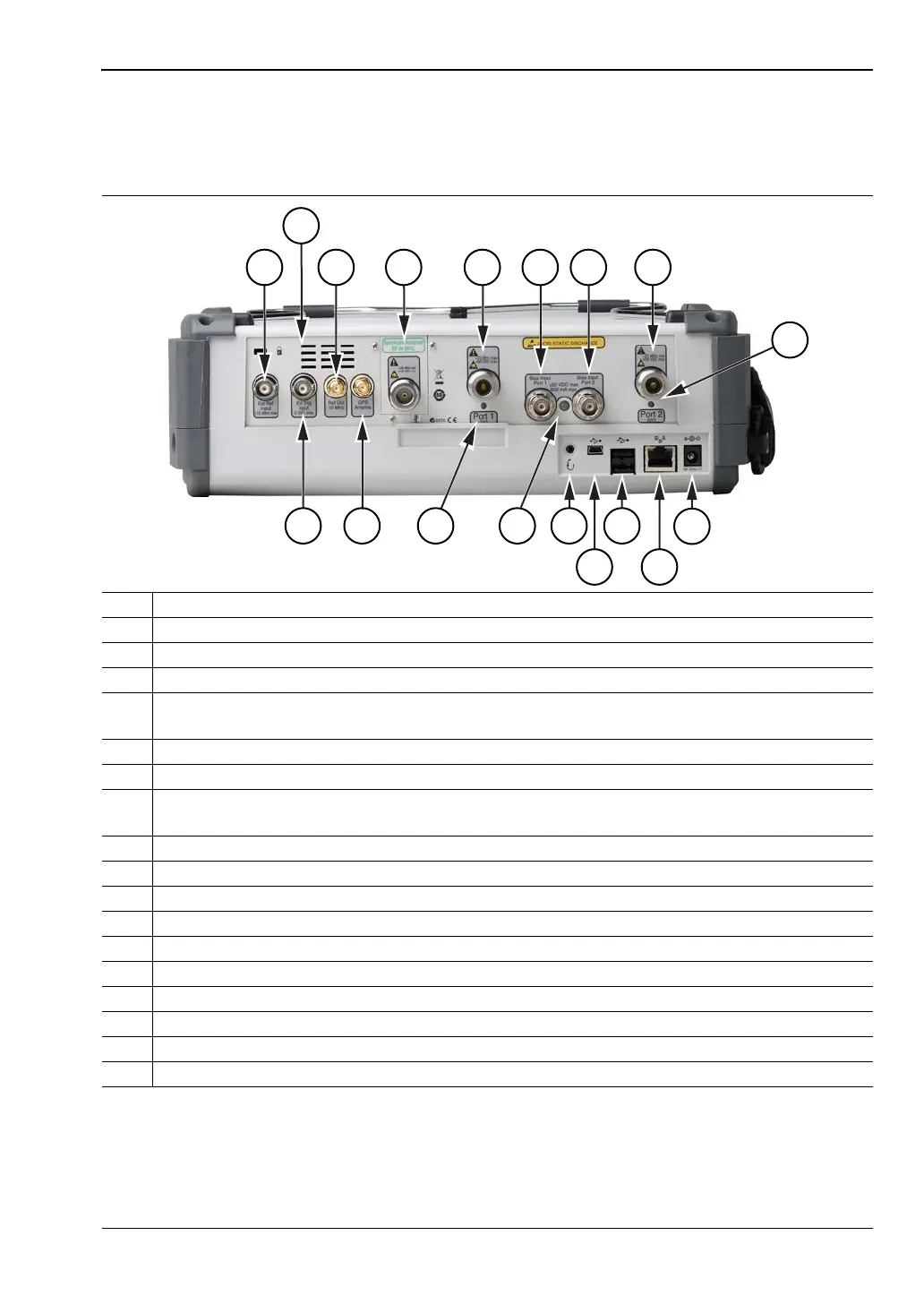
MS203xC Test Panel Connectors
The connectors and indicators that are located on the test panel of the MS2036C, MS2037C,
and MS2038C are shown in Figure 2-14 and are described in the table below the figure.
1 External Reference Input
2Fan Exhaust Port
3 Reference Out (10 MHz)
4 Spectrum Analyzer RF Input (50 ohm)
5 Test Port 1 (50 ohm)
The corresponding LED turns green when the port is transmitting.
6 Bias Input Port 1
7 Bias Input Port 2
8 Test Port 2 (50 ohm)
The corresponding LED turns green when the port is transmitting.
9 Port 2 LED
10 External Power Input
11 LAN Connection
12 USB Interface, Type A (2 connectors, Full Speed USB 2.0)
13 USB Interface, Type Mini-B (Full Speed USB 2.0)
14 Headset Jack
15 Bias Status LED
16 Port 1 LED
17 GPS Antenna Input for Option 31
18 External Trigger Input
Figure 2-14. MS203xC Test Panel Connectors
3 4
5 6
7 8
15
1
1417 12
11
13
18
2
16
10
9
ООО "Техэнком" Контрольно-измерительные приборы и оборудование www.tehencom.com