SECTION 3 – USER INTERFACE
2014-APR-30 REV. 0 PAGE 3-1
USER INTERFACE
This section provides the user with overall information on
features and operation of the CHECKFIRE 110 Control
Module.
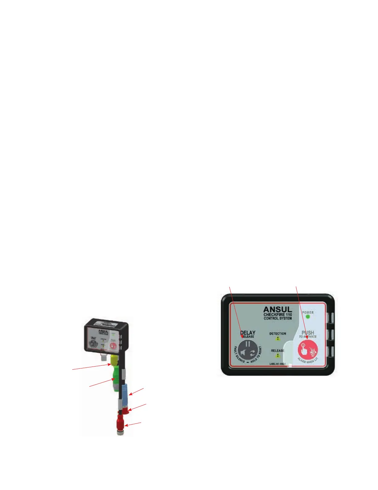
FIELD CONNECTIVITY – Cables and Devices
The CHECKFIRE 110 Control Module communicates to
devices through cable assemblies incorporating IP67 circu-
lar threaded connectors with color-coded overmolding. See
Figure 3-1.
IP67 is an environmental ingress protection rating. The first
number indicates protection from solid objects (0 is no special
protection, 6 is protection from dust). The second number is
protection against liquids (0 is no protection, 7 is protection
against the effect of immersion in water).
Detection Circuit Lead
Release Circuit Lead
External Power Circuit Lead (12/24 VDC)
Alarm Circuit Lead (Auxiliary Devices)
FIGURE 3-1
CONTROL MODULE LEADS
CONTROL MODULE FRONT PANEL BUTTONS
“DELAY/Reset/Silence” Button
Manage fault and/or detection conditions by pressing the
-
ing results:
• Audible Fault Silence
o Silence an audible notification during a fault condition for
the fault condition has been cleared. If a subsequent fault
condition occurs, the audible notification will resume until
fault has cleared.
the sounder.
audible notification.
o The audible notification for either a post-discharge or fault
condition will resume after being silenced for two hours.
• Restart Time Delay Sequence
(must be initiated before release circuit activation occurs).
• Control Module Reset
Reset the control module after initiating devices have been
restored and/or reset.
• Select Time Delay Period
FIGURE 3-2
CONTROL MODULE FRONT PANEL
CHECKFIRE 110
Detection and Actuation System
OUTPUT
POWER