SECTION 4 – SYSTEM PLANNING
Detection Circuit Cable (Red Connectors) (Continued)
-
3. Connect directly to Detection Circuit Cable or connect to
Linear Detector assemblies.
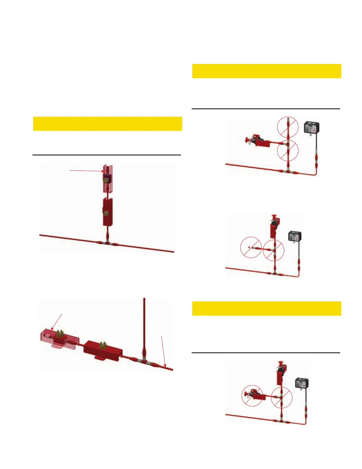
4. Spot thermal detectors may be run in a branch from main
installed on a branch. See Figure 4-4.
CAUTION
FIGURE 4-4
SPOT THERMAL DETECTOR BRANCH INSTALLATION
EOL DEVICE
FIGURE 4-5
SPOT THERMAL DETECTOR MAIN TRUNK INSTALLATION
Review complete plan layout for the following INCORRECT
INSTALLATIONS and adjust as needed.
CAUTION
Do not use an EOL Device on a branch because the complete
Failure to comply may cause the system to not function properly.
NO EOL DEVICE
FIGURE 4-6
INCORRECT EMA INSTALLATION
ON SINGLE USE
NO EOL DEVICE
FIGURE 4-7
INCORRECT INSTALLATION
CAUTION
ON SINGLE USE
FIGURE 4-8
INCORRECT EMA INSTALLATION
CHECKFIRE 110
Detection and Actuation System