SECTION 8 – RECHARGE, INSPECTION, AND MAINTENANCE
2014-MAY-01 REV. 01 PAGE 8-5
CHECKFIRE 110
Detection and Actuation System
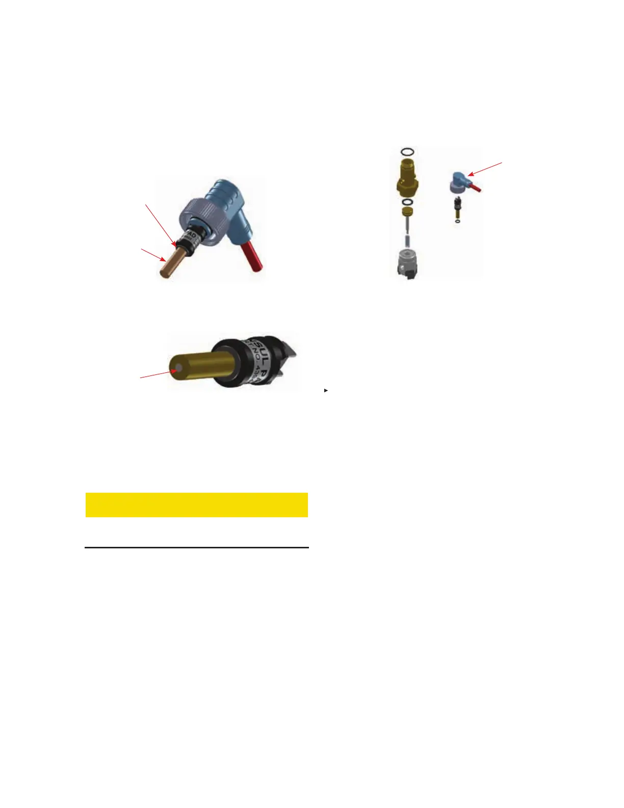
PAD O-RING
CHECK PAD
IF PIN IS VISIBLE
PAD HAS
ACTUATED
RELEASE CIRCUIT
DROP CABLE
CONNECTOR
MAINTENANCE (Continued)
e. If PAD actuated, remove PAD from the connector and
discard. If possible, determine why PAD was actuated.
Do not install new PAD until testing is complete,
see Step 9. Find and discard small brass disk ejected
from actuating end of PAD during release.
FIGURE 8-7
CHECK PAD
009246
FIGURE 8-8
CHECK END OF PAD
009243
f. If needed, remove 1/4 in. gas actuation hose(s). Loosen
and slide base of Electric-Pneumatic Actuator sideways
to remove from each expellant gas cartridge.
CAUTION
If Electric-Pneumatic Actuator is difficult to remove
puncture pin is not fully retracted. Do not force.
g. Disassemble actuator and inspect for damage. Using
small wood dowel gently push puncture pin and spring
out of body being careful not to bend puncture pin.
Retain all parts for re-assembly. See Figure 8-9.
FIGURE 8-9
ELECTRIC-PNEUMATIC ACTUATOR
RETAIN ALL PARTS FOR RE-ASSEMBLY
009244
h. Inspect and replace all damaged components (i.e.
o-rings, flat gaskets, etc.).
i. Lubricate all o-rings and gaskets with Dow Corning #4
(or equal) and reinstall. Include o-ring on PAD.
j. Replace flat gasket semi-annually.
k. Install spring on puncture pin and insert into body. Push
down several times to confirm ease of movement.
l. Reassemble actuator.
m. Install actuator cap (if needed) and pressure test using
dry air or nitrogen.
7. Re-install Electric-Pneumatic Actuator on expellant gas
cartridge. See Section 5 – Installation, page 5-9 and 5-10
for correct procedure.
8. Test system and place into service by completing all steps
in Section 6 - Test and Place in Service. Note: If Release
Circuit Fault LED indicates an un-intentional fault condition,
there may be an open or grounded circuit. Replace cables
as needed.
9. For fire suppression system maintenance refer to appropri-
ate system manual (latest edition)
• LT-A-101-10/20/30 Manual (Part No. 24327)
• LT-A-101-50/125/250 Manual (Part No. 427865)
• LVS Manual (Part No. 427109)
10. Confirm all system equipment has been properly serviced
and recharged, and visual inspection seals are in place on
all EMAs and CHECKFIRE 110 Control Module.
11. Record date of maintenance on tag and in permanent
record file. Notify operating personnel system is back in
service.