SECTION 5 – INSTALLATION
PAGE 5-6 REV. 02 2014-MAY-08
CHECKFIRE 110
Detection and Actuation System
General Instructions for Cable Installation (Continued)
4. Adjust slack to avoid droops in cable. Allow appropriate
slack through areas that are intended to move under normal
vehicle operation.
5. When cables pass through a partition, it is recommended
to use a bulkhead connector designed for the appropriate
cables. Note: Cables must never be routed through
a hole or near sharp edges without being properly
protected. See Figure 5-14.
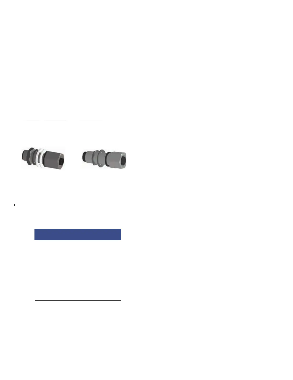
Bulkhead Connectors
Maximum
Pass-through
Part No. Thickness Cable Type
439404 3/8 in. (9.5 mm) Detection Circuit
439405 1 in. (25 mm) Release Circuit
Power Circuit
DETECTION CIRCUIT RELEASE CIRCUIT AND POWER CIRCUIT
BULKHEAD CONNECTOR BULKHEAD CONNECTOR
FIGURE 5-14
BULKHEAD CONNECTORS
009159 / 009166
LINEAR DETECTOR INSTALLATION
Install Linear Detector throughout the hazard area by connect-
ing directly to the main detection trunk. Note: Linear Detector
should not be supported by hydraulic hoses.
NOTICE
The minimum bend radius for Linear
Detector must not be less than 2 1/2 in.
(64 mm) (see Figure 5-16, page 5-7). Adjust
slack to avoid droops in cable. Allow appropri-
ate slack through areas that are intended to
move under normal vehicle operation.
• Do not try to stretch Linear Detector in any
way.
• Do not attach Linear Detector to commonly
removed or replaced equipment.
Note: Linear Detector must connect to main Detection Circuit
trunk, not the branch of a Detection Circuit Tee.
Keep the following in mind when installing a Linear Detector:
• Make certain Linear Detector routing allows direct exposure
to heat resulting from a fire
• Choose routing locations where heat is likely to travel to or
through quickly in event of a fire
• Maximum installed ambient temperature at the Linear Detec-
tor location is 250 °F (121 °C).
• Support Linear Detector from mounting surfaces such as
decks, struts, framework, vehicle component support, or
support structures, etc., always keeping system planning
guidelines and vehicle maintenance procedures in mind.
Note: When supporting from the vehicle make certain any
support device requiring drilling or welding is approved by
owner or vehicle manufacturer.
• Avoid securing Linear Detector too close to extremely hot
components
• Route the Linear Detector where it will not be subject to
damage and not interfere with vehicle maintenance proce-
dures.
• Keep Linear Detector as far away as possible from vehicle
electric cables, particularly power cables to and from genera-
tors and electric motors.
1. Make sure detection circuit cable is completely installed
from CHECKFIRE 110 Control Module to hazard area end
point. Start installation of Linear Detector at end point of
detection circuit cable.
2. Install Linear Detector above hazard area or around perim-
eter of a hazard compartment so it can react to escaping
heat. Refer to layout drawing. Do not allow struts, frame
members, or other obstacles to act as heat shields between
hazard and detector cable.
3. Do NOT install Linear Detector within 12 in. (305 mm) of
any area that will become extremely hot during operation,
such as:
• Engine blocks
• Exhaust manifolds
• Exhaust tubes/Mufflers
• Turbochargers
4. Secure Linear Detector every 12 in. to 18 in. (305 mm to
454 mm) using appropriately sized (5/16 in. (8 mm)) rubber-
lined P-Clamps. Where it is not possible to use rubber
lined P-Clamps, a double-loop cable tie (Part No. 440737)
and protective covering (Part No. 56692) is acceptable
to provide separation between cable and securing point.
Secure more often if necessary
Slice rubber tube length wise to fit around the Linear Detec-
tor. This protective covering should also be used at loca-
tions where cable would rub against other hard surfaces,
rough edges, or sharp corners. See Figure 5-15.