SECTION 5 – INSTALLATION
2014-MAY-08 REV. 02 PAGE 5-7
CHECKFIRE 110
Detection and Actuation System
LINEAR DETECTOR INSTALLATION (Continued)
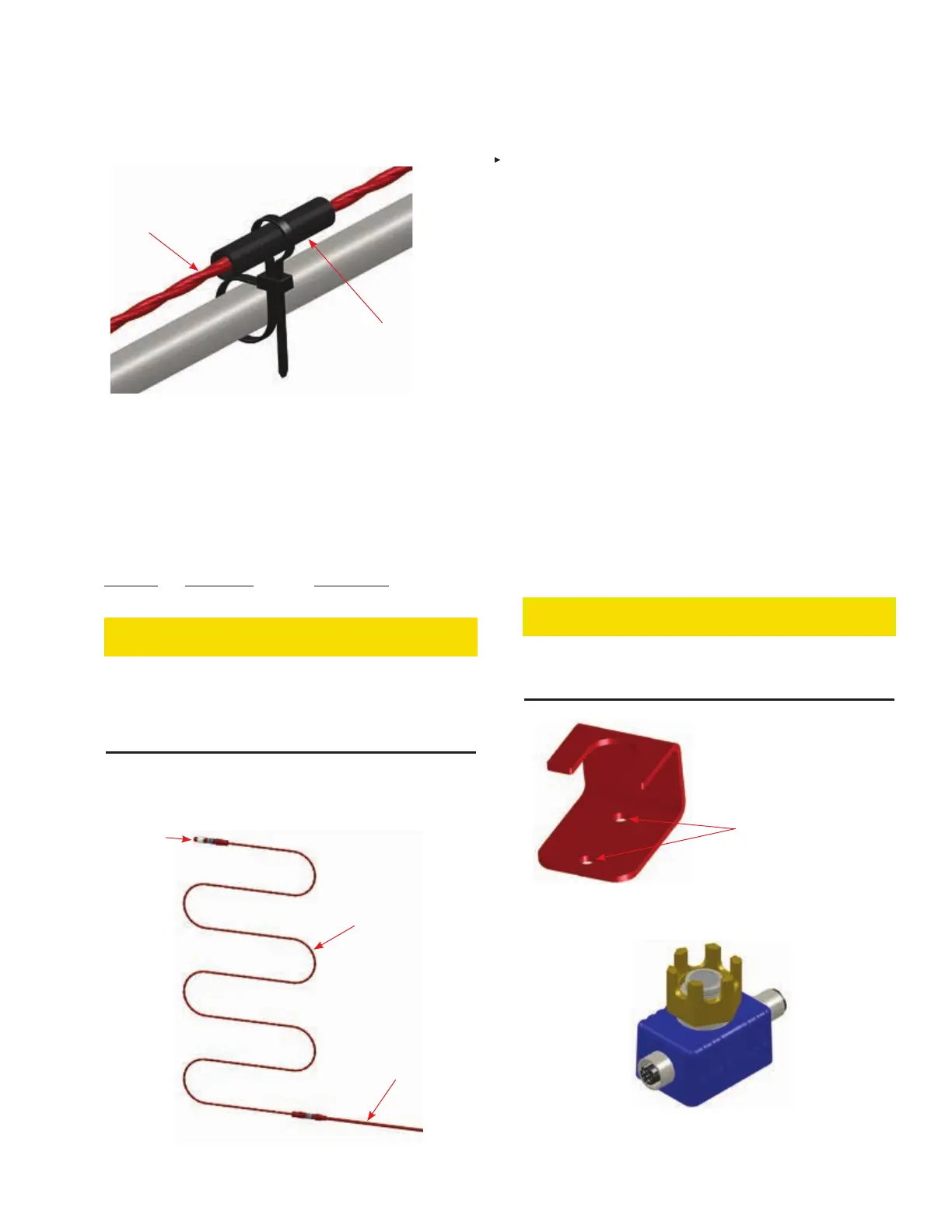
LINEAR
DETECTOR
PROTECTIVE
COVERING
FIGURE 5-15
DOUBLE-LOOP CABLE TIE
009213
5. When a Linear Detector must pass-through a partition it is
recommended to use a bulkhead fitting designed for the
appropriate cable. See Figure 5-14, page 5-6.
Bulkhead Connector
Maximum
Pass-through
Part No. Thickness Cable Type
439404 3/8 in. (9.5 mm) Detection Circuit
CAUTION
Linear Detector must never be routed through a hole or near
sharp edges without being properly protected. Failure to
protect the cable from being cut or abraded could cause a
fault condition or false alarm condition, potentially leading to
a false discharge or detection failure.
6. Install an EOL Device (Part No. 439396) at end of the
Linear Detector, if last device, to complete the circuit. See
Figure 5-16.
BEND RADIUS
NOT LESS THAN
2.5 IN. (64 mm)
MAIN DETECTION
CIRCUIT
EOL DEVICE
FIGURE 5-16
SAMPLE LINEAR DETECTOR INSTALLATION
009194
SPOT THERMAL DETECTOR INSTALLATION
Mount in a location where detector head points in a downward
position with exposure over the hazard area (refer to layout
drawing).
1. Attach Spot Thermal Detector Bracket securely to mount-
ing surface by welding or bolting with two 1/4 in. bolts of
appropriate length (secure with lock washers and nuts). See
Figure 5-17. Note: When supporting from the vehicle make
certain any support device requiring drilling or welding is
approved by owner or vehicle manufacturer.
2. After securing bracket, remove retaining nut from detector
head and slide detector in bracket. Confirm detector has
male/female connectors in correct position for connection to
detection circuit cable. See Figure 5-18.
3. Place Heat Shield over detector head and loosely install
retaining nut. See Figure 5-19. Note: Remove Heat Shield
to connect Detection Circuit Cables.
4. During final installation, apply a medium-strength thread-
locking compound (e.g. LOCTITE THREADLOCKER BLUE
242) to the base of threaded detector head near the heat
shield.
5. Tighten retaining nut wrench-tight until the retaining nut is
snug. Do not over tighten. Torque not to exceed 25 in-lb
(2.82 N•m).
CAUTION
Over tightening of the retaining nut can damage the detec-
tor. Do not overtighten. Torque not to exceed 25 in-lb (2.82
N•m).
MOUNTING HOLES FOR
1/4 IN. MOUNTING BOLTS
(OR WELD)
FIGURE 5-17
SPOT THERMAL DETECTOR BRACKET
009234
FIGURE 5-18
SPOT THERMAL DETECTOR
009280