SECTION 5 – INSTALLATION
2014-APR-30 REV. 0 PAGE 5-13
RELEASE CIRCUIT CABLES
The Release Circuit Lead (Blue connector) on the CHECK-
FIRE 110 Control Module is the starting point for the release
circuit. See Figure 5-40. The Release Circuit consists of a
main trunk, Release Circuit Tee (if required), and Release
Circuit Drop Cable(s). Note: Release Circuit maximum length
is 50 ft (15.24 m).
FIGURE 5-40
CHECKFIRE 110 CABLES
009150
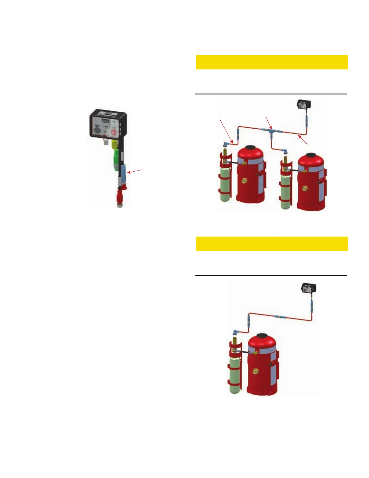
Install Release Circuit using the following rules (see Figure
5-41 and 5-42):
1. Maximum two PADs.
2. Maximum 50 ft (15.2 m) of Release Circuit Cable. (Cable
dimensions include the connectors.)
3. Use a Release Circuit Tee for second PAD if needed. Addi-
tional Release Circuit Cable may be used after the tee if
required.
4. Use Release Circuit Drop Cable at end of circuit for connec-
tion to the Electric-Pneumatic Actuator.
5. Route and secure Release Circuit Cable following instal-
lation instructions under Cable Connectivity / Installation,
page 5-4. (Remove and discard dust cap on Release Circuit
Lead.)
6. Do not attach Release Circuit Drop Cable to Electric-Pneu-
matic Actuator at this time. If Release Circuit Drop Cable
is connected, the system could be actuated accidentally
during installation.
CAUTION
DO NOT ATTACH RELEASE CIRCUIT DROP CABLE TO
ELECTRIC-PNEUMATIC ACTUATOR UNTIL TESTING IS
COMPLETE.
FIGURE 5-41
RELEASE CIRCUIT - TWO TANKS
009225
CAUTION
DO NOT ATTACH RELEASE CIRCUIT DROP CABLE TO
ELECTRIC-PNEUMATIC ACTUATOR UNTIL TESTING IS
COMPLETE.
FIGURE 5-42
RELEASE CIRCUIT - SINGLE TANK
009226
CHECKFIRE 110
Detection and Actuation System
RELEASE
CIRCUIT LEAD
WITH DUST CAP
NOTE: CABLES SHOWN
SHORTER THAN
ACTUAL LENGTH
SINGLE TANK – NO
TEE REQUIRED
RELEASE
CIRCUIT CABLE
RELEASE
CIRCUIT TEE
RELEASE CIRCUIT
DROP CABLE