SECTION 9 – TROUBLESHOOTING
2014-APR-30 REV. 0 PAGE 9-5
CHECKFIRE 110
Detection and Actuation System
TABLE 9-5: SPECIFIC CIRCUIT TESTING PROCEDURES (Continued)
Power Circuit
If Power LED is pulsing AMBER or showing no indication for
more than 30 seconds check external power connections.
Required Test Equipment
• New Fuse (3 amp inline ATO/ATC blade style automotive
fuse)
• Digital Multimeter
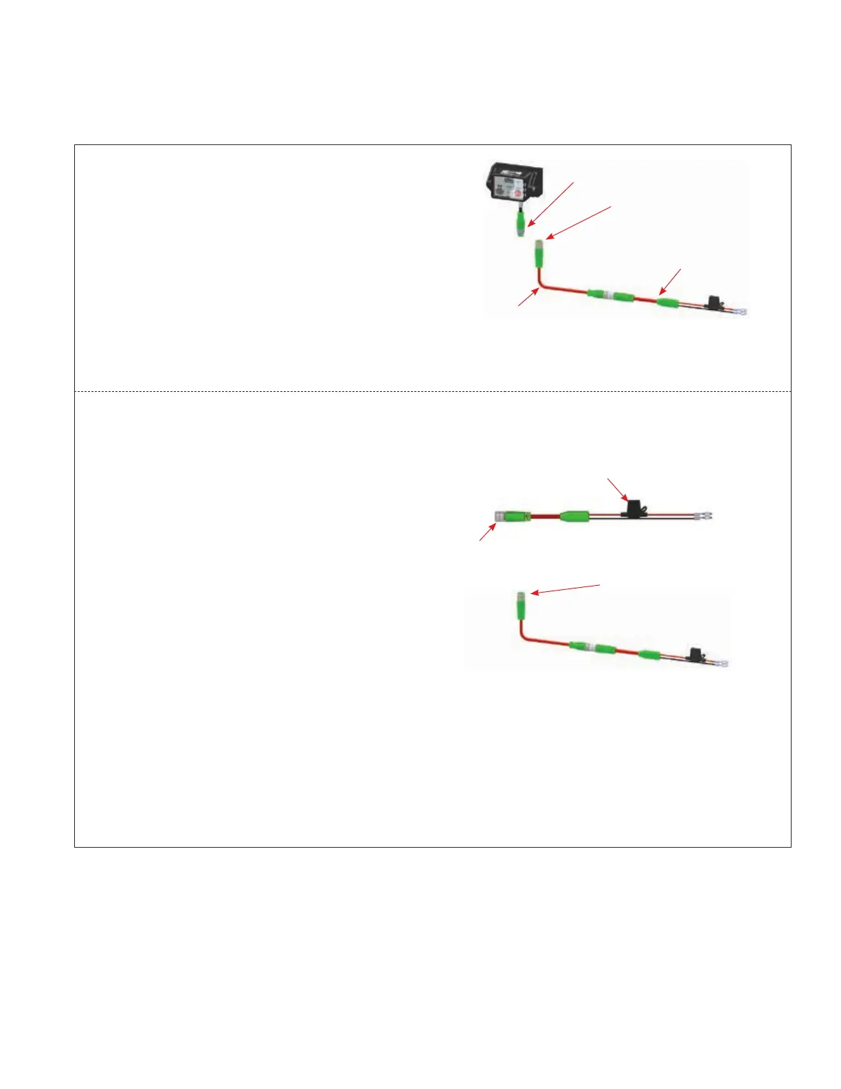
1. Disconnect Power Circuit Cable at the control module
power circuit lead (green connector). Use the Digital Multi-
meter to confirm proper voltage is available at the end of
the Power Circuit Cable. If voltage on Power Circuit Cable
is correct, there is a control module internal problem and
the CHECKFIRE 110 Control Module must be replaced.
2. If voltage on Power Circuit Cable is not correct, use the
Digital Multimeter to check for proper voltage at the vehicle
power source (battery).
a. If voltage is correct move to step 3.
b. If power source voltage is incorrect or indicates no
power, contact vehicle service personnel to correct.
When voltage is restored reconnect entire power circuit
to see if power fault clears. If fault does not clear return
to step one.
3. Check fuse in the Fused Power Circuit Cable connected
to vehicle power source. If needed replace fuse following
instructions in Section 5 – Installation, page 5-14 (step 5).
4. After confirming correct voltage at the power source
and a good fuse, disconnect Fused Power Circuit Cable
connector from power circuit and check for proper voltage
with the Digital Multimeter. If voltage on Fused Power
Circuit Cable is correct, the cable is functioning properly.
If voltage is incorrect the Fused Power Circuit Cable must
be replaced.
5. After confirming correct voltage at end of Fused Power
Circuit Cable continue checking the remaining power
circuit at each set of connectors for proper voltage from
the power source. Replace non-functioning cable with an
identical new part.
Continues Next Page
1. CHECK FOR PROPER
VOLTAGE; IF CORRECT
REPLACE MODULE
FUSED POWER
CIRCUIT CABLE
POWER
CIRCUIT LEAD
POWER
CIRCUIT CABLE
009248
4. CONFIRM VOLTAGE
AT CONNECTOR
3. CHECK FUSE, IF
NEEDED REPLACE
2. CONFIRM CORRECT
VOLTAGE AT
POWER SOURCE
FOLLOW SECTION 5 – INSTALLATION
INSTRUCTIONS TO REPLACE FUSE
009173
5. CONFIRM VOLTAGE
AT EACH SET OF
CONNECTORS
009248