SECTION 9 – TROUBLESHOOTING
PAGE 9-6 REV. 0 2014-APR-30
CHECKFIRE 110
Detection and Actuation System
TABLE 9-5: SPECIFIC CIRCUIT TESTING PROCEDURES (Continued)
Power Circuit (Continued)
6. After replacing non-functioning cable and confirming
correct voltage through entire power circuit, reconnect to
Control Module. Power LED returns to GREEN steady-on.
If all faults are clear, verify proper operation of the
CHECKFIRE 110 System by completing Section 6 – Test
and Place in Service.
Note: Specific jurisdictions or customer procedures may
require documentation of all components replaced. Keep a
record of all changes to the system as required.
Release Circuit
If Release Circuit Fault LED is pulsing AMBER and cannot be
cleared check release circuit cable.
Required Test Equipment (Confirm test equipment is new
and functioning properly)
• 2 - Release Circuit Terminators (Part No. 439436)
• 2 - Release Circuit Test Plugs (Part No. 440912)
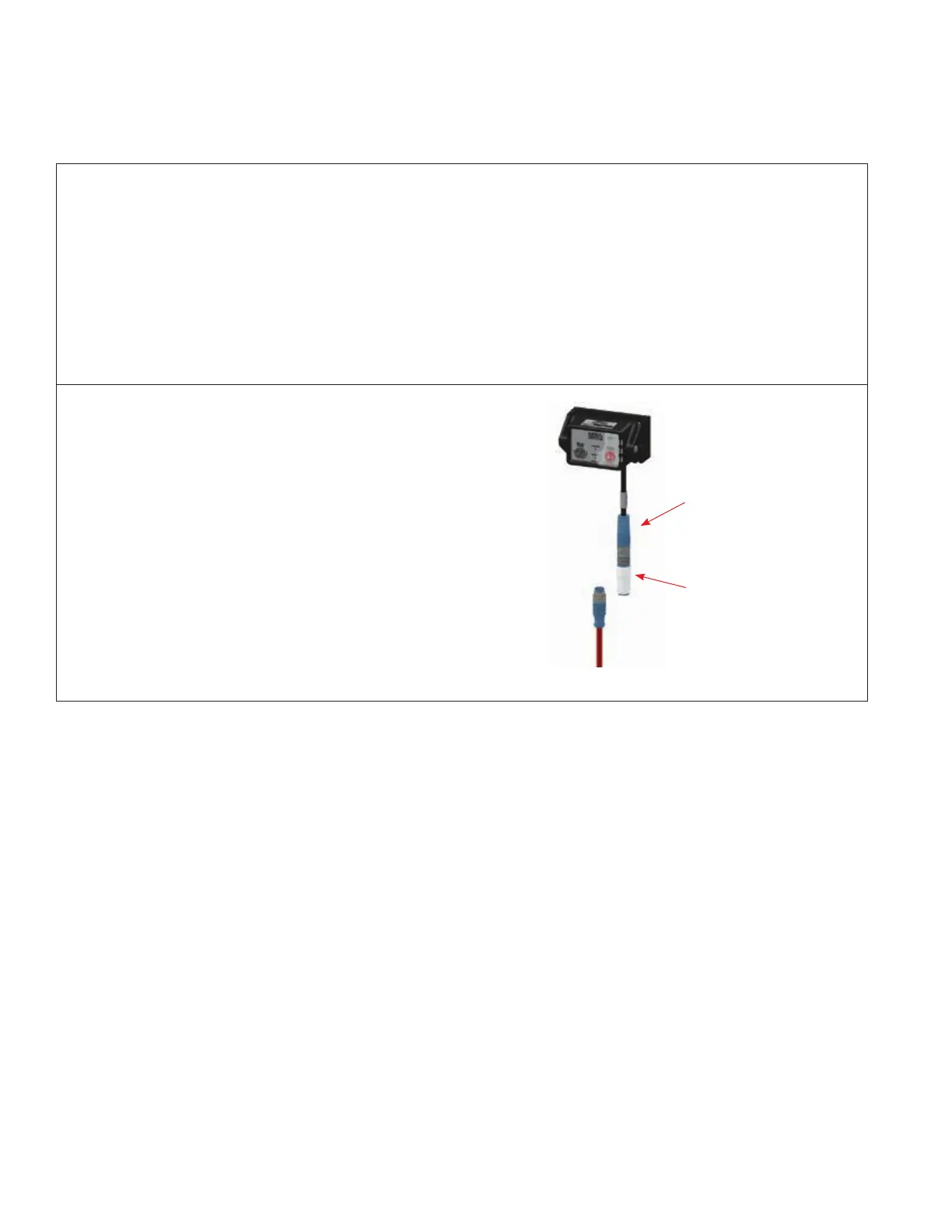
1. Disconnect Release Circuit Cable at the control module
release circuit lead (blue connector). Install Release Circuit
Terminator on the blue lead. If Release Circuit Fault LED
continues pulsing AMBER, there is a control module inter-
nal problem and the CHECKFIRE 110 Control Module
must be replaced.
Continues Next Page
RELEASE
CIRCUIT LEAD
1. INSTALL
TERMINATOR; IF
FAULT CONTINUES
REPLACE MODULE
009249