SECTION 4 – SYSTEM PLANNING
Detection Circuit Cable (Red Connectors) (Continued)
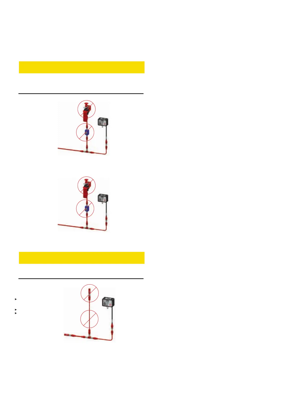
CAUTION
and on a single use branch. Failure to comply may cause the
ON SINGLE USE
FIGURE 4-9
INCORRECT EMA INSTALLATION
ON SINGLE USE
FIGURE 4-10
INCORRECT EMA INSTALLATION
CAUTION
Do not install the Linear Detector on a branch. (See Figure
4-11).
DEVICE
FIGURE 4-11
INCORRECT INSTALLATION
Release Circuit Cable (Blue Connectors)
Connects Electric-Pneumatic Actuator(s) (for agent tank expel-
-
tors (one per tank).
actuator near the operator and/or in path of egress at a point
accessible from ground level. Refer to appropriate system
manual list on page 2-2.
1. Determine location of agent tank(s), expellant gas cartridge
assembly(s), and actuator(s) for specific cable end points.
2. Plan route for the release circuit cable from the control
module to the agent tank expellant gas cartridge end
point(s) (note end point(s) for cable lengths). Choose a path
in accessible locations providing protection from undue
-
and from generators and electric motors; also avoid:
-
nance personnel
3. Select appropriate cable lengths for area of installation.
Circuit Cable to interconnect release circuits.
CHECKFIRE 110
Detection and Actuation System