EasyManuals Logo
Home>Ansul>Control Systems>CHECKFIRE 110

Ansul CHECKFIRE 110 User Manual

Ansul CHECKFIRE 110
88 pages
To Next Page IconTo Next Page
To Previous Page IconTo Previous Page
Page #25 background imageLoading...
Page #25 background image
SECTION 4 – SYSTEM PLANNING
 
Detection Circuit Cable (Red Connectors)
Connects input devices to the CHECKFIRE 110 Control

 
 
 
1. Determine appropriate detection method (linear detectors
or spot thermal detectors) and placement for specific cable
end points. Review specific requirements for each at the
end of this section.
2. Choose a path providing protection for the cable, keep the

-
tric motors; also avoid:
 
 
 
 
 
 

 -
nance personnel
3. Plan route for the cable from the control module to the
detection component end points (note end points for cable

 
 
 

 
 
 

 
4. Select appropriate cable lengths for area of installation.
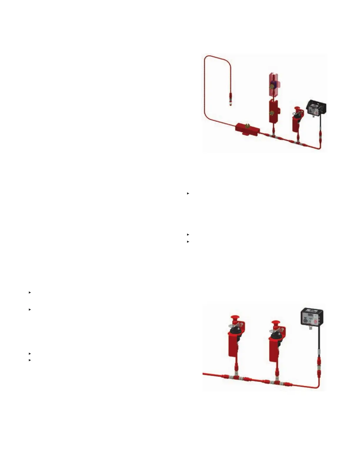

-


FIGURE 4-1
CORRECT DETECTION CIRCUIT INSTALLATION





in. (6.3 mm) maximum thickness) or bracket mount on a flat


 

detection circuit. See Figure 4-2.
 
accessible from ground level. If intended for vehicle oper-

easily accessible to operator.
 


FIGURE 4-2
CORRECT EMA INSTALLATION

CHECKFIRE 110
Detection and Actuation System

Table of Contents

Other manuals for Ansul CHECKFIRE 110

Questions and Answers:

Question and Answer IconNeed help?

Do you have a question about the Ansul CHECKFIRE 110 and is the answer not in the manual?

Ansul CHECKFIRE 110 Specifications

General IconGeneral
BrandAnsul
ModelCHECKFIRE 110
CategoryControl Systems
LanguageEnglish

Related product manuals