SECTION 5 – INSTALLATION
PAGE 5-2 REV. 0 2014-APR-30
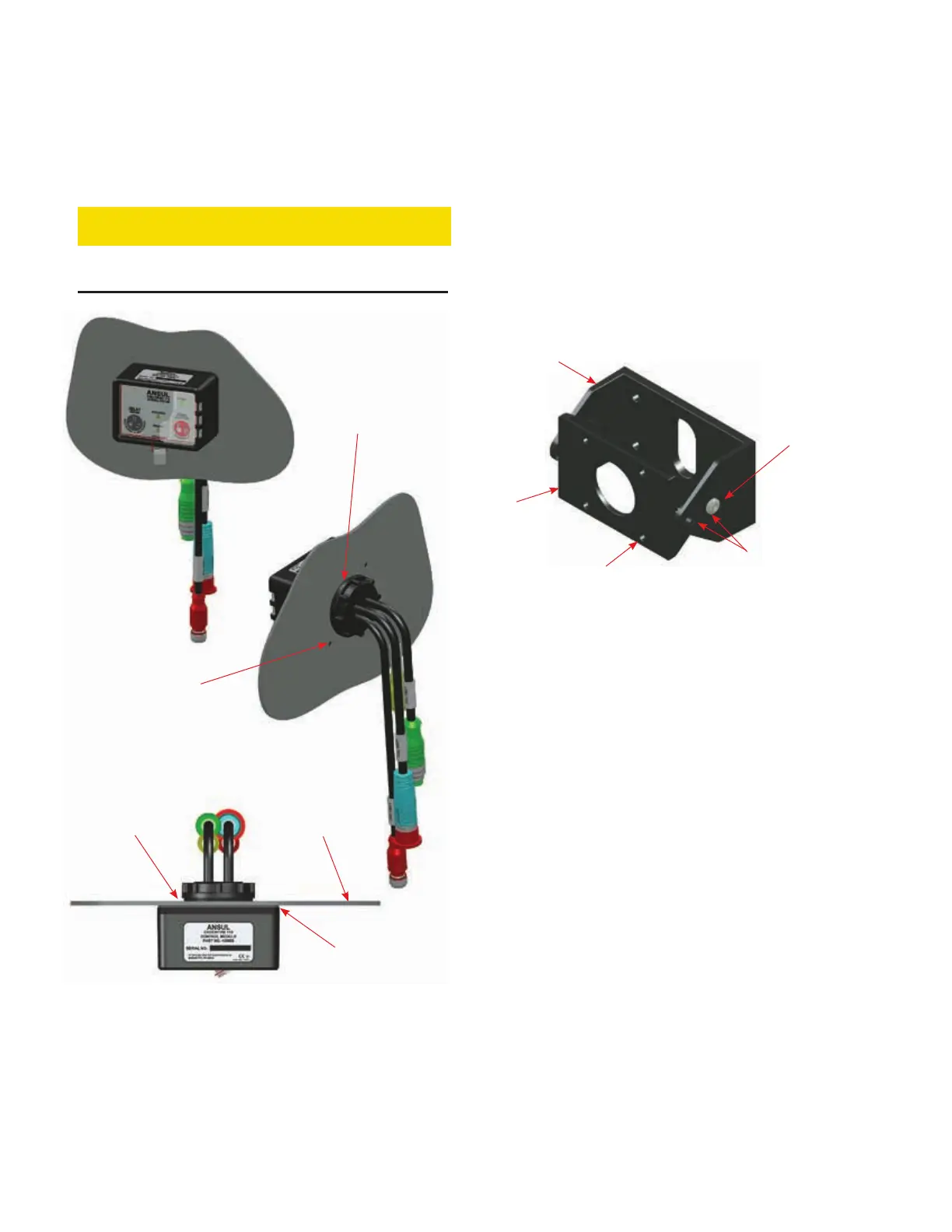
Surface Mounting Instructions (Continued)
8. Hand-tighten enclosure nut on threaded boss, see Figure
5-3.
CAUTION
Only hand-tighten enclosure nut, do not use mechanical
force such as a wrench.
FIGURE 5-3
SURFACE MOUNT 110 CONTROL MODULE
009205
Bracket Mounting Instructions
Bracket mounting requires the CHECKFIRE 110/210 Mount-
ing Bracket (Part No. 439564). The bracket is a two piece,
multi-position bracket for securing the control module in a
variety of configurations. Mount on a flat surface that will prop-
erly support the control module during all vehicle operating and
environmental conditions (e.g. shock and vibration).
The bracket includes a Bracket Base, a Swivel Mount and
two swivel joint screws, see Figure 5-4. The control module
attaches to swivel mount in a horizontal or vertical position on
either side of swivel mount.
FIGURE 5-4
CHECKFIRE 110/210 MOUNTING BRACKET
009181
1. Refer to layout drawing for planned location and determine
a position within the operator’s reach with the best viewing
angle for control module LEDs and easy access to control
module buttons. Verify the location meets approval of the
vehicle owner and/or vehicle service manager. See Figure
5-5 for sample mounting options. Note the positions of
swivel mount and connectors.
CHECKFIRE 110
Detection and Actuation System
HAND-TIGHTEN
ENCLOSURE NUT
INDEX HOLES
(TWO PLACES)
RUBBER
WASHER
MAXIMUM 3/16 IN.
(4.7 mm) THICKNESS
FOAM GASKET
FORWARD AND
BACK CONNECTORS
(FOUR PLACES)
SWIVEL JOINT
SCREW (TWO
PLACES)
BRACKET BASE
SWIVEL
MOUNT
INDEX HOLE
(FOUR PLACES)