SECTION 3 – USER INTERFACE
CONTROL MODULE FRONT PANEL BUTTONS (Continued)
Red “PUSH To Activate / Alarm When Lit” Button and LED
Indicator (See Figure 3-2)
-
Note: No time delay occurs when red “PUSH To Activate /
After 10 seconds, the control module enters post-discharge
a detection signal, the “PUSH To Activate / Alarm When
Table 3-1):
(release circuit active) (sounder remains steady-on).
(sounder matches pulse rate).
Internal Sounder (Audible Notification)
(see Table 3-1)
CHECKFIRE 110
Detection and Actuation System
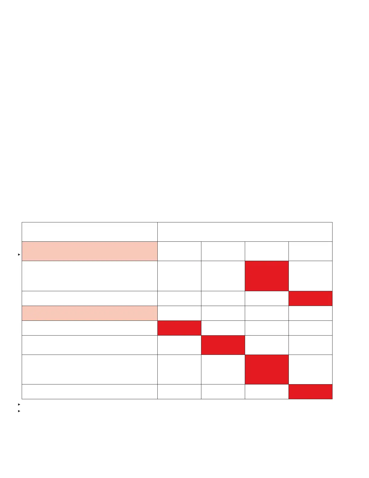
“PUSH To Activate / Alarm When Lit”
LED and Sounder Indications
Manual Action
(Release Circuit Activation)
2 x 1 sec.
for 10 sec.
4 x 1 sec.
for 5 sec.
Steady-on
for 10 sec.
1 x 10 sec.
until reset*
Or: Pull ring pin and push an EMA
(Immediate release for either action)
Post discharge
Detection Circuit Input
And
Release Circuit Activation
Post discharge
TABLE 3-1: SUMMARY DETECTION CONDITION INDICATORS
* Release Fault Indicator also pulses at this rate during post discharge. When release circuit test device is installed,
Release Fault Indicator does not pulse.