SECTION 8 – RECHARGE, INSPECTION, AND MAINTENANCE
2014-MAY-01 REV. 01 PAGE 8-3
RECHARGE (Continued)
FIGURE 8-4
RETRACT ACTUATOR PISTON
009220
b. Re-install Electric-Pneumatic Actuator on expellant gas
cartridge. See Section 5 – Installation, page 5-9 and
5-10 for correct procedure.
9. Reconnect the CHECKFIRE 110 Control Module Release
Circuit Lead to release circuit. Release Circuit Fault clears
once all faulty components have been replaced. Note: If
Release Circuit Fault LED indicates an un-intentional fault
condition, there may be an open or grounded circuit. Refer
to Section 9 – Troubleshooting to determine cause of fault.
Replace cables as needed.
10. Test system and place into service by completing all steps
in Section 6 - Test and Place in Service.
11. Complete steps 1 – 3 in the Maintenance Section.
12. Confirm all system equipment has been properly serviced
and recharged, and visual inspection seals are in place on
all EMAs and CHECKFIRE 110 Control Module.
13. Record date of recharge on tag and in permanent record
file. Notify operating personnel system is back in service.
INSPECTION AND MAINTENANCE
To help ensure the CHECKFIRE 110 Detection and Actuation
System will operate as intended, proper inspection and mainte-
nance procedures must be performed at the specified intervals.
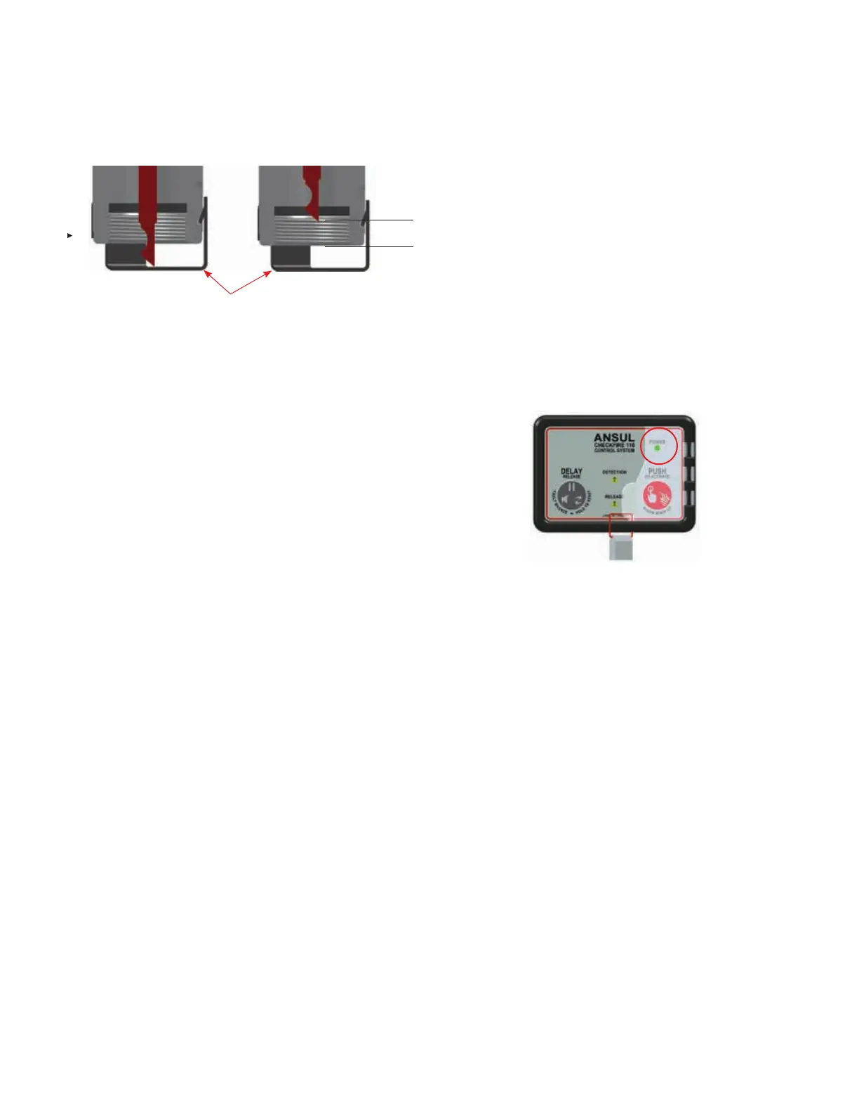
DAILY INSPECTIONS
The vehicle operator must check the system daily by visually
verifying:
• Power LED is GREEN and steady-on, see Figure 8-5
• All other LEDs are off (not steady-on or pulsing)
• Sounder is silent
If any other conditions exist, contact the local Authorized
ANSUL Distributor or a person who has been trained and
authorized by Tyco Fire Protection Products to perform inspec-
tion and maintenance service on the CHECKFIRE 110 System.
FIGURE 8-5
NORMAL CONDITION
009151
MAINTENANCE
To help ensure the system will operate as intended, mainte-
nance shall be performed semi-annually or sooner, depending
on the operating and/or environmental conditions. Maintenance
should be performed by an Authorized ANSUL Distributor or
a person who has been trained and authorized by Tyco Fire
Protection Products to perform maintenance checks.
Visually inspect system to confirm it is adequate for the vehicle
hazard areas.
1. Check condition of the CHECKFIRE 110 Control Module.
a. Confirm securely mounted, either in the CHECKFIRE
110/210 Mounting Bracket or surface mounted. Verify
all fasteners are tight and control module Enclosure Nut
is hand-tight.
b. If secured in bracket, check bracket for damage or wear
to ratchet teeth.
c. Check control module for damage or undue wear.
CHECKFIRE 110
Detection and Actuation System
PIN NOT RETRACTED PIN COMPLETELY RETRACTED
PREVENTOR
1/4 IN.
(6.4 mm)