SECTION 4 – SYSTEM PLANNING
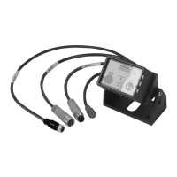
CHECKFIRE 110
Detection and Actuation System
Power Circuit Cables (Green Connectors)
supply).
(note end points for both cables). Choose a path in acces-
from generators and electric motors; also avoid:
-
nance personnel
3. Select appropriate cable lengths for area of installation. See
Alarm Output Circuit Lead – Digital 3.3 VDC
-
tor is positive and the black conductor is negative.
intended to directly operate analog devices such as audible
use the circuit as a logic input to a vehicle operating system or
cooling fans, hydraulic pumps, notification devices, relays, etc.
Note:
Lead may compromise the IP67 rating for this circuit.
NOTICE
is intended for use.
Vehicle System Pressure Switch
-
be used to perform several different tasks on system actuation,
-
field connections.
Planner/Installer must verify contact ratings of devices intended
direct instruction and approval.
Note:
Label Package
procedures of the system to vehicle operators.
System Layout
Once components are selected and locations are determined,
-
tified.
Use circuit bulkhead connectors to support and protect cables.
-
avoid installation problems later.
Compile a list of components to confirm system includes all
components combine to provide automatic fire detection and
activation of the fire suppression system for protected areas.

 Loading...