SECTION 5 – INSTALLATION
PAGE 5-4 REV. 0 2014-APR-30
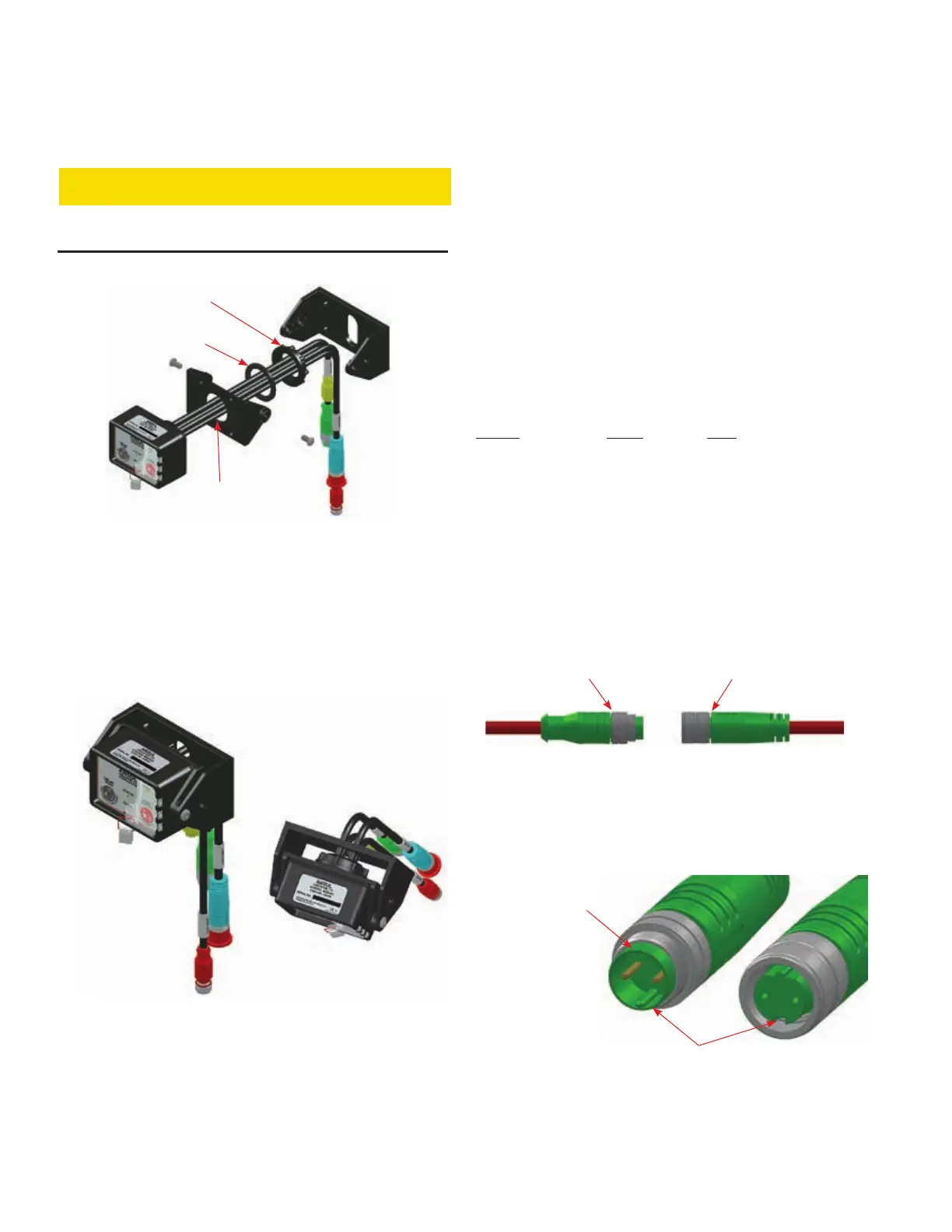
Bracket Mounting Instructions (Continued)
CAUTION
The enclosure nut should only be hand-tightened, do not use
mechanical force (such as a wrench).
FIGURE 5-7
ENCLOSURE NUT
009206
7. If required, feed cables through opening in bracket base.
Reinstall the Swivel Mount to the base according to the
position determined in Step 1. Carefully align joint teeth and
secure with the swivel joint screws to lock swivel mount in
place. Do not over tighten, 20-25 in-lbs (2.26-2.82 N•m)
maximum. See Figure 5-8.
FIGURE 5-8
MOUNTING BRACKET WITH
CHECKFIRE 110 CONTROL MODULE
009207
CABLE CONNECTIVITY / INSTALLATION
The CHECKFIRE 110 System utilizes IP67 circular threaded
connectors on all cable and tee components. This modular
cable harness reduces installation time and damaged cables
can be replaced without replacing the entire cable assembly.
The cable assemblies have a red outer jacket between
threaded connectors.
For easy recognition of each cable type, the integral connec-
tors have color-coded overmolding. Specific pin and key
designs help ensure proper cable connections.
Note: Refer to the layout drawing for circuit routing and
cable/tee assembly.
CIRCUIT CABLE IDENTIFICATION
Circuit Color Pins
Detection RED 4
Release BLUE 2
External Power GREEN 2
Alarm Output YELLOW N/A
Connector Assembly
Organize cables, tees, and associated connectors for each
circuit. Assemble cables by connecting the male and female
connectors. The male end has connector pins and a threaded
swivel nut. The female end has sockets and a swivel connec-
tor, see Figure 5-9.
FIGURE 5-9
CABLE CONNECTORS
009208
1. Align the male end with the female end by positioning keyed
slots and pins in the proper orientation, see Figure 5-10.
FIGURE 5-10
ALIGN PINS AND KEYS
009209
CHECKFIRE 110
Detection and Actuation System
RUBBER
WASHER
ENCLOSURE
NUT
PULL CABLES
THROUGH CENTER
OPENING
PINS
MATCH KEYED
SLOTS AND PINS
TO CONNECT
CABLES
MATCHING SLOTS
SWIVEL CONNECTOR AND SOCKET
SWIVEL NUT AND PINS
MALE END FEMALE END