SECTION 1 – SYSTEM DESCRIPTION
2014-AUG-28 REV. 02 PAGE 1-1
SYSTEM DESCRIPTION
The CHECKFIRE 110 Detection and Actuation System is typi-
cally used with an ANSUL A-101 or LVS Vehicle Fire Suppres-
sion System for 24-hour protection of equipment. The system
is designed for vehicles in extreme environmental and physical
conditions.
Industries Where Vehicles Use CHECKFIRE 110 Systems:
• Forestry
• Agriculture
• Construction
• Public transportation
• Public utilities
• Land fills
• Waste disposal
• Mining
The automatic detection and actuation system provides moni-
tored input/output circuits to activate an ANSUL fire suppres-
sion system. On detecting a fire condition, the control module
activates the release circuit resulting in the discharge of an
expellant gas cartridge initiating fire suppression system opera-
tion. Optional pneumatic actuation is available.
CHECKFIRE 110 Features
• Supervised power, detection, and release circuits
• External primary power with an internal reserve power
source
• Selectable release time delay
• Electric “DELAY/Reset/Silence” button
• “PUSH To Activate / Alarm When Lit” electric manual activa-
tion button
• Color-coded “Plug and Play” connections
• 85 dB Internal Sounder
• System isolate feature
• Dust and water tight (IP67 rated)
CHECKFIRE 110 Specifications
CONTROL MODULE POWER (24 HOUR OPERATION)
12/24 VDC vehicle primary power source
Internal 72 hour reserve power source
SYSTEM CURRENT DRAW
Nominal < 6 mA @ 10.2 – 28 VDC
• Maximum < 100 mA @ 10.2 – 28 VDC
OPERATING TEMPERATURE LIMITS
– 40 °F to 140 °F (– 40 °C to 60 °C)
APPROVALS
FM Approved and CE Marked
CHECKFIRE 110 Connectivity
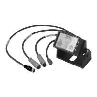
The modular cable harness system includes four color-coded
leads for Detection, Release, External Power, and Alarm
Output. See Figure 1-1.
DETECTION INITIATING / MANUAL ACTIVATION CIRCUIT
Detection circuit lead - 33 in. (838 mm) with Red color-coded
connector
Connects to:
• Detection Circuit Cable
- Electric Manual Actuator
- Linear Detector
- Spot Thermal Detector
RELEASE CIRCUIT
Release circuit lead – 27 in. (686 mm) with Blue color-coded
connector
Connects to:
• Release Circuit Cable
- Release Circuit Drop Cable
EXTERNAL POWER CIRCUIT
Power circuit lead – 21 in. (533 mm) with Green color-coded
connector
Connects to:
• Power Circuit Cable
- Fused Power Circuit Cable
ALARM OUTPUT CIRCUIT (Optional)
Alarm circuit lead – 16 in. (406 mm) with Yellow color-coded
plug
Connects to:
• Vehicle electronics (digital 3.3 VDC output)
FIGURE 1-1
CHECKFIRE 110 CONTROL MODULE LEADS
009150
CHECKFIRE 110
Detection and Actuation System
EXTERNAL
POWER
RELEASE
DUST CAP
DETECTION
VISUAL SEAL
NOTE: CABLES SHOWN
SHORTER THAN
ACTUAL LENGTH
3.3 VDC
ALARM OUTPUT

 Loading...