SECTION 6 – TEST AND PLACE IN SERVICE
PAGE 6-6 REV. 0 2014-APR-30
CHECKFIRE 110
Detection and Actuation System
TABLE 6-4: OPERATIONAL TEST
The following tests verify system operation for:
1. Circuit Supervision: Confirm supervisory function of each
circuit.
2. Detection Input: Receive electrical signal from a detection
device (simulated fire condition).
3. Time Delay: Verify accuracy of time delay setting.
4. Spot Thermal Detectors: Verify contact closure.
5. Electric Manual Activation: Receive electrical signal from
an EMA.
If noted results are not attained, refer to Section 9 -
Troubleshooting for corrective action.
NOTICE
If the system is connected to a vehicle shut-
down device through the pressure switch,
verification needs to be made at the pres-
sure switch.
NOTICE
During testing, verify any devices connected
to the Alarm Circuit Lead function as
intended.
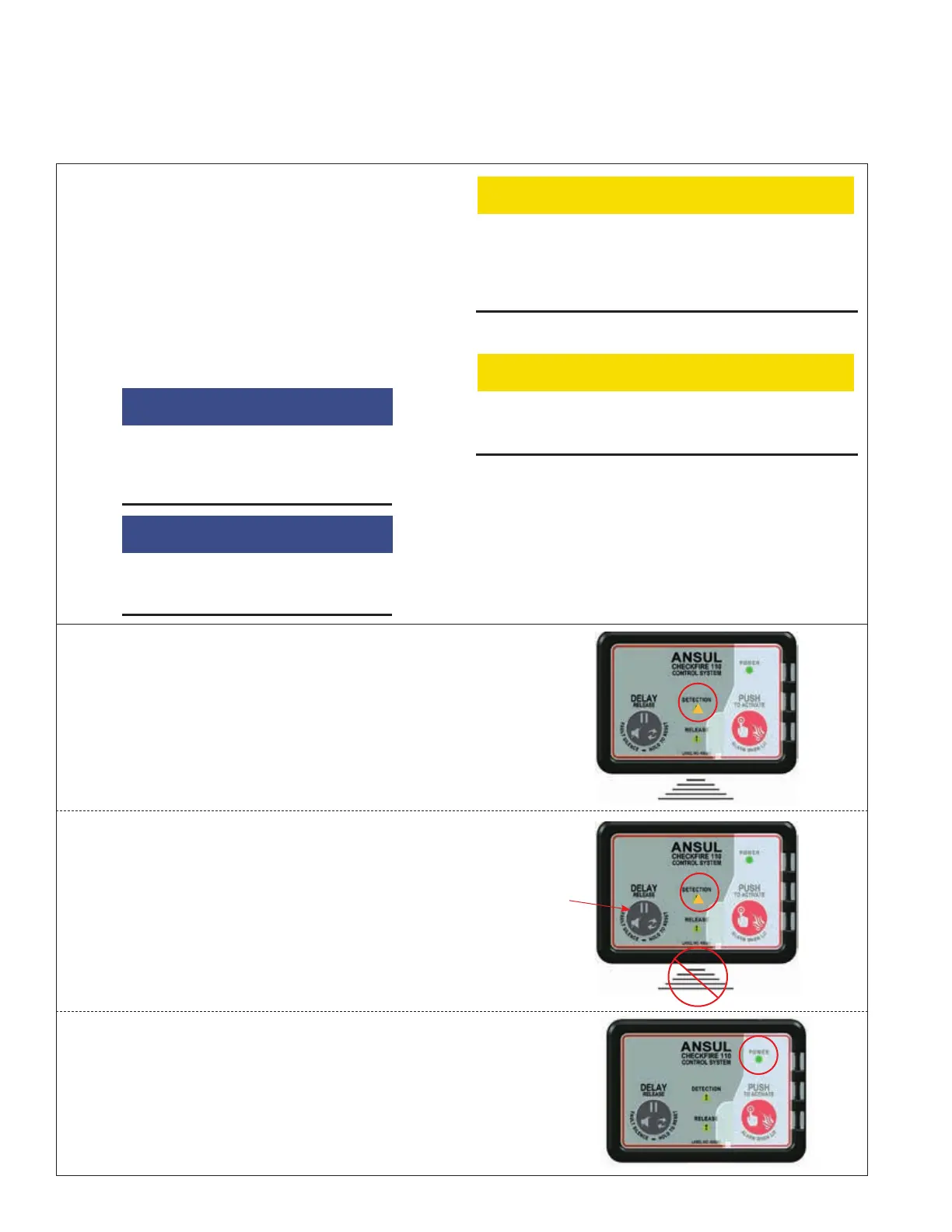
Detection Circuit - Supervision Test
Set DCT switch to “Fault” position. The CHECKFIRE 110
Control Module indicates the following:
1. Detection Fault LED pulses AMBER 1 x 10 seconds.
2. Sounder pulses 1 x 10 seconds.
Test silence function: push the “DELAY/Reset/Silence”
button.
3. Sounder silences and Detection Fault LED continues to
pulse AMBER 1 x 10 seconds.
Reset the DCT to the “Normal” position.
4. CHECKFIRE 110 Control Module returns to Normal
status; Power LED is GREEN steady-on.
CAUTION
Before performing any operational test(s), protect the fire
suppression system from unintentional actuation. Verify
Electric-Pneumatic Actuators are not connected to Release
Circuit Drop Cables and any pneumatic manual actuators are
ring-pinned for safety and/or actuation cartridges removed.
CAUTION
When performing any operational testing, make certain the
RCT (Part No. 441021) and Release Circuit Test Plug(s) (Part
No. 440912) are attached to the release circuit.
009180
RESET DCT TO
NORMAL
MODULE RETURNS
TO NORMAL
STATUS
POWER LED IS
GREEN STEADY-ON
009180b
DETECTION FAULT
INDICATION (DCT
SWITCH = FAULT)
AMBER LED
AND SOUNDER
PULSE 1 X 10
SECONDS
!
009180b
SILENCE FUNCTION
DETECTION FAULT
INDICATION
PUSH TO
SILENCE
SOUNDER (LED
CONTINUES)
AMBER LED
PULSES 1 X 10
SECONDS
!