SECTION 5 – INSTALLATION
2014-MAY-01 REV. 01 PAGE 5-1
INSTALLATION
Before installing the detection and actuation system, Section 4
- System Planning should be studied in its entirety. In addition,
a resulting system layout drawing with information on hazard
areas, component locations, and routing of connecting circuits,
along with all cable lengths identified, should be available.
Review this drawing and become familiar with all applicable
steps and instructions before installing any component.
NOTICE
For ease of installation, the fire suppression
system should be installed before the detec-
tion and actuation system.
CHECKFIRE 110 CONTROL MODULE INSTALLATION
The CHECKFIRE 110 Control Module may be surface
mounted (3/16 in. (4.7 mm) maximum thickness) or bracket
mounted. For bracket mounting, use the CHECKFIRE 110/210
Mounting Bracket (Part No. 439564). Index pins on the control
module prevent rotating. Note: The Control Module should
--never be mounted in an area subject to pressure washing or
steam cleaning.
Surface Mounting Instructions
Although recommended, the CHECKFIRE 110 Control Module
does not require a bracket when surface mounting in a flat
location. The location must properly support the control module
during all vehicle environmental and operating conditions (e.g.
shock and vibration).
1. Refer to layout drawing for planned location and determine
a position within operator’s reach with the best viewing
angle for control module LEDs and easy access to control
module buttons. Verify the location meets approval of the
vehicle owner and/or vehicle service manager.
2. Confirm access to underside or rear of mounting surface to
enable proper cable connections, periodic inspections, and
maintenance. Verify control module location and connec-
tions will not interfere with normal vehicle operation, service,
and maintenance.
3. Drill three holes matching the correct diameter and layout
for surface mounting, see Figure 5-1.
a. Use the foam gasket as a template to carefully mark
hole locations. The gasket has 4 index holes (for ease
of installation) and the control module has 2 index pins.
Before drilling, make sure index holes on the gasket line
up correctly with the index pins on the control module.
See Figure 5-2.
Note: The foam gasket is packaged in a separate bag
with the enclosure nut, rubber washer, and visual seal
in the CHECKFIRE 110 Shipping Assembly (Part No.
439559).
b. After drilling holes, remove burrs and sharp edges.
4. Install foam gasket on control module.
a. Remove protective backing exposing gasket adhesive.
b. Align with index pins on back of control module and
press in place, securing to control module surface.
FIGURE 5-1
SURFACE MOUNTING TEMPLATE
(FOAM GASKET)
009203
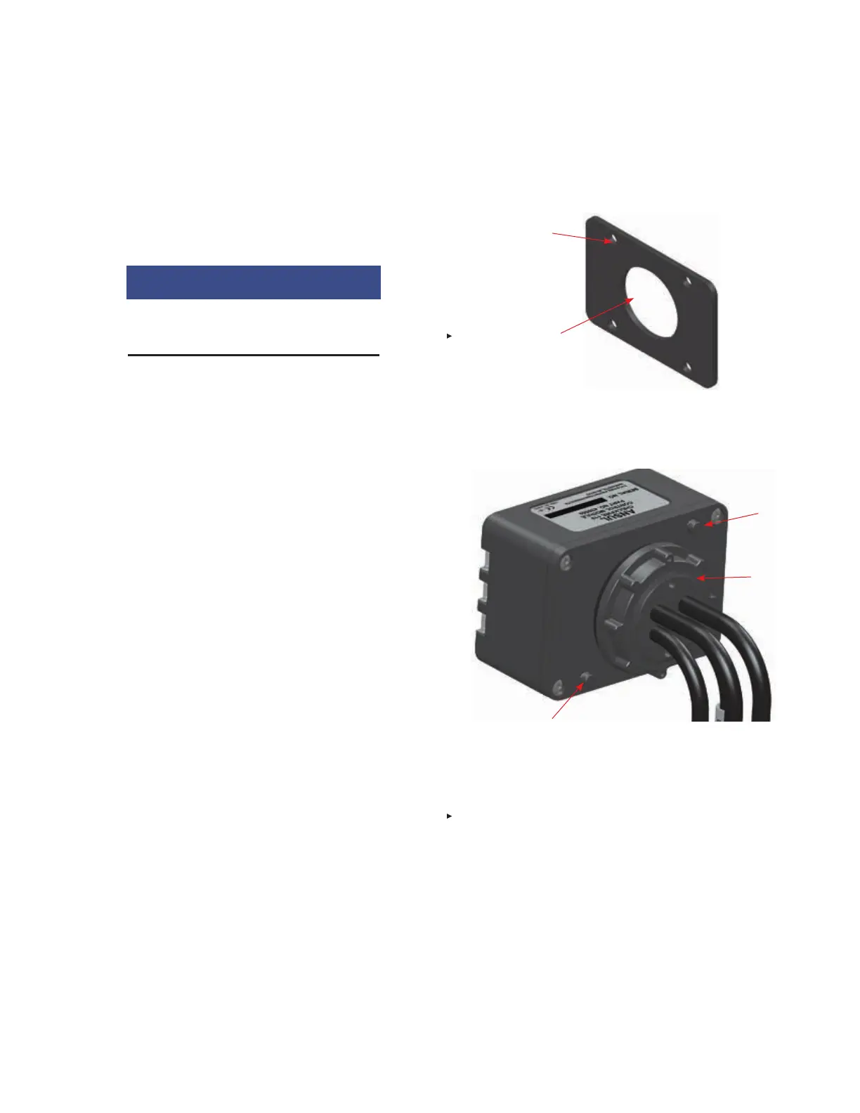
FIGURE 5-2
INDEX PINS AND THREADED BOSS
009204
5. If possible, hold rubber washer and enclosure nut (pack-
aged in separate bag) on the back side of the mounting
surface so it lines up with the 1 9/16 in. (40 mm) drilled
hole.
6. Carefully feed cables through drilled hole, rubber washer,
and enclosure nut.
7. Fit index pins and threaded boss into the drilled holes.
CHECKFIRE 110
Detection and Actuation System
1 9/16 IN. (40 mm)
HOLE FOR CABLES
AND THREADED
BOSS
1/4 IN. (6 mm) HOLE
FOR CONTROL
MODULE INDEX PINS
(FOUR PLACES)
NOTE: ONLY DRILL TWO 1/4
IN. (6.3 mm) HOLES FOR INDEX
PINS – MATCH WITH PINS ON
MODULE
INDEX
PIN
INDEX PIN
THREADED
BOSS