EasyManuals Logo

Ansul CHECKFIRE 110 User Manual

Ansul CHECKFIRE 110
88 pages
To Next Page IconTo Next Page
To Previous Page IconTo Previous Page
Page #21 background imageLoading...
Page #21 background image
SECTION 3 – USER INTERFACE
2014-APR-30 REV. 0 PAGE 3-3
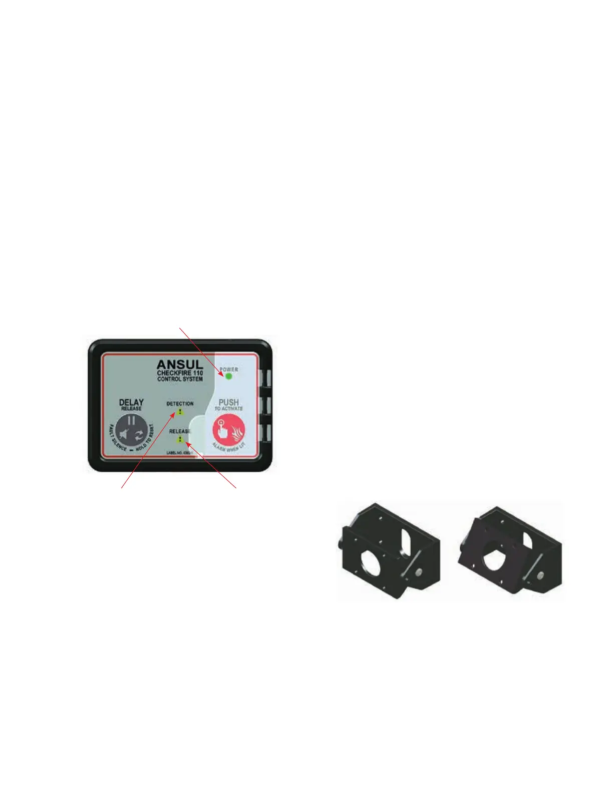
CONTROL MODULE FRONT PANEL INDICATORS
Power Status (Dual-Color Power LED – GREEN / AMBER)
(See Figure 3-3)
 

source
 
-
able level causing a fault condition. Note: sounder matches
pulse rate for 10 minutes, then auto-silences to conserve
energy
 

down
 

sounder will cease (may take up to 30 seconds)
FIGURE 3-3
CONTROL MODULE FRONT PANEL

Detection Circuit Fault (AMBER) (See Figure 3-3)
 
rate) during a fault condition
 
Release Circuit Fault (AMBER) (See Figure3-3)
 
rate) during a fault condition
 
POWER
External Power (Primary)
The CHECKFIRE 110 Control Module utilizes vehicle power


power conditions such as open circuits, and/or ground faults.
Internal Reserve Power
In the event primary power source is low or disconnected
the CHECKFIRE 110 Control Module has an internal reserve
power source providing up to 72 hours of reserve power. A low

-

power source will clear the fault and automatically regenerate
the internal power source.
CONTROL MODULE MOUNTING
Two types of mounting options are available.
 

to fasten the control module in place without a bracket. The
foam gasket minimizes moisture and dust ingress though the
opening.
 

filled nylon material. The pivot and secure feature accommo-
dates easy operator visual identification and access to the
CHECKFIRE 110 Control Module for status indications and
manual operation. See Figure 3-4.
Note: The Control Module should never be mounted in an area
subject to pressure washing or steam cleaning.
FIGURE 3-4
CONTROL MODULE BRACKET

CHECKFIRE 110
Detection and Actuation System





POWER GREEN OR


Table of Contents

Other manuals for Ansul CHECKFIRE 110

Questions and Answers:

Question and Answer IconNeed help?

Do you have a question about the Ansul CHECKFIRE 110 and is the answer not in the manual?

Ansul CHECKFIRE 110 Specifications

General IconGeneral
BrandAnsul
ModelCHECKFIRE 110
CategoryControl Systems
LanguageEnglish

Related product manuals