•
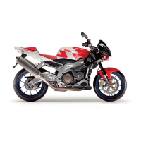
Using an Allen spanner on the related
seat (1), lock the rotation of the threa-
ded pin (2), unscrew and remove the
self-locking nut (3) and the threaded
pin (2).
THE SELF-LOCKING NUTS (3) MUST BE REPLACED EV-
ERY THREE CROWN GEAR REMOVALS.
REPLACE THE SELF-LOCKING NUTS (3) WITH NUTS OF
THE SAME TYPE.
•
Remove the sprocket mounting (4).
•
Clean the sprocket (5) and the sprock-
et mounting (4) with fresh detergent.
Reassembly:
•
Fit the five threaded pins (2) on the
sprocket (5).
•
Install the sprocket mounting on the
sprocket mounting - threaded pin as-
sembly.
•
Hand-tighten the five self-locking nuts
(3).
NEVER INSTALL THE FINAL TRANSMISSION UNIT (6) ON
THE WHEEL TO TIGHTEN THE SELF-LOCKING NUTS.
TO PROTECT THE CROWN GEAR, INSTALL PROTEC-
TIONS ON THE JAWS OF THE VICE (IN WOOD OR ALUMI-
NIUM). SECURE ONLY THE CROWN GEAR IN THE VICE,
DO NOT BLOCK ANY OTHER COMPONENT OF THE FINAL
DRIVE ASSEMBLY.
•
Lock crown gear in a vice.
CAUTION
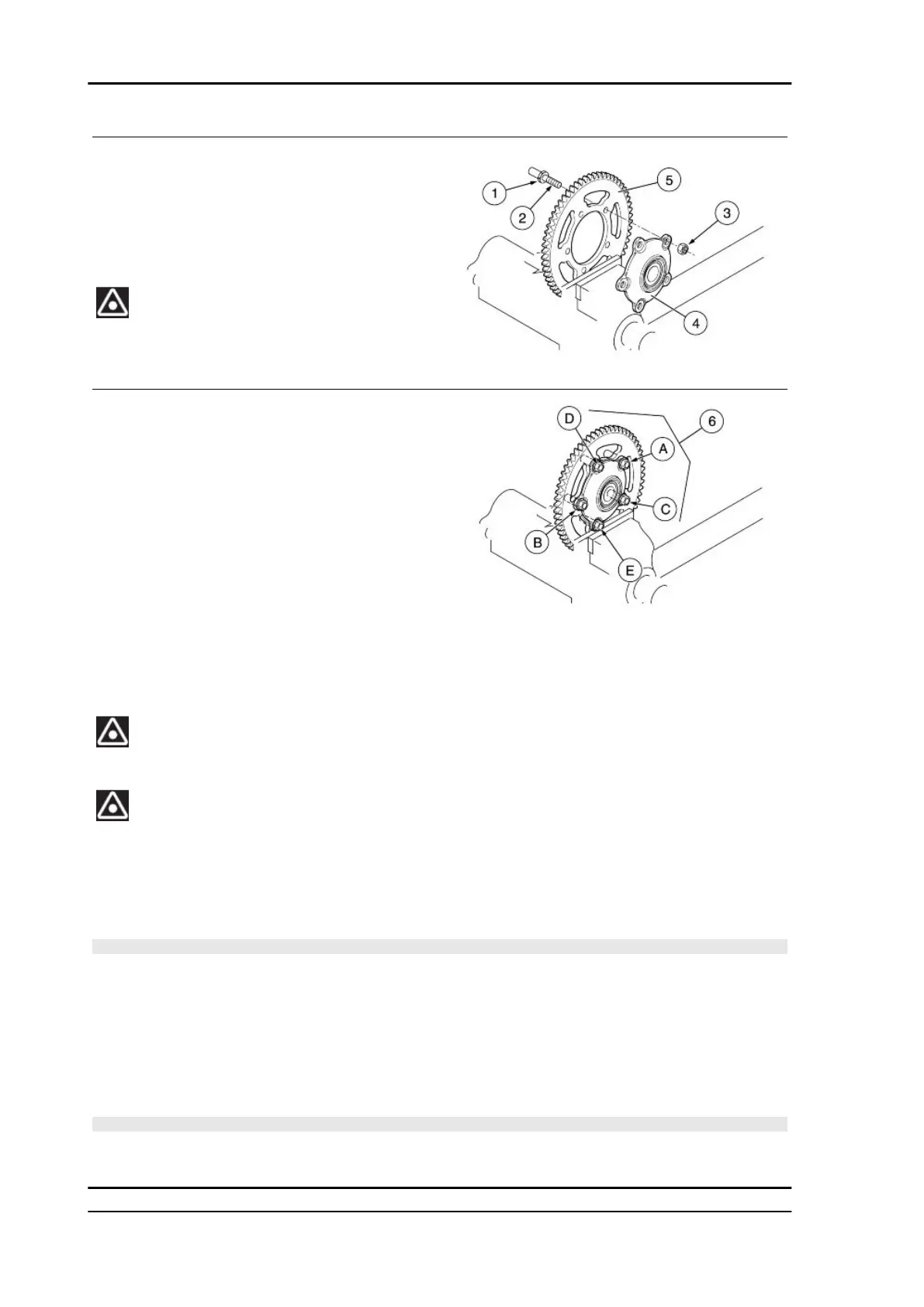
TO AVOID POTENTIAL DISTORTIONS AND/OR INCORRECT COUPLING, TIGHTEN AS FOL-
LOWS:
•
Using an Allen key on the specific seat (1), lock the rotation of the threaded pin (2), and
applying half the specified torque, tighten the diametrically opposed elements in this se-
quence: (A) (B) (C) (D) (E).
•
Repeat the previous operation, applying the specified tightening torque.
CAUTION
IN THIS WAY THE PRESSURE EXERTED BY THE FIXING ELEMENTS WILL BE EVENLY DIS-
TRIBUTED ON THE COUPLING SURFACE.
Suspensions TUONO V4 R a-PRC ABS
SUSP - 416

 Loading...