Chapter 2: Installation
4 1X-X3 Installation Manual
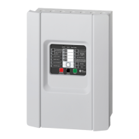
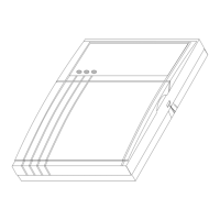
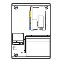
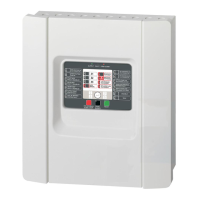
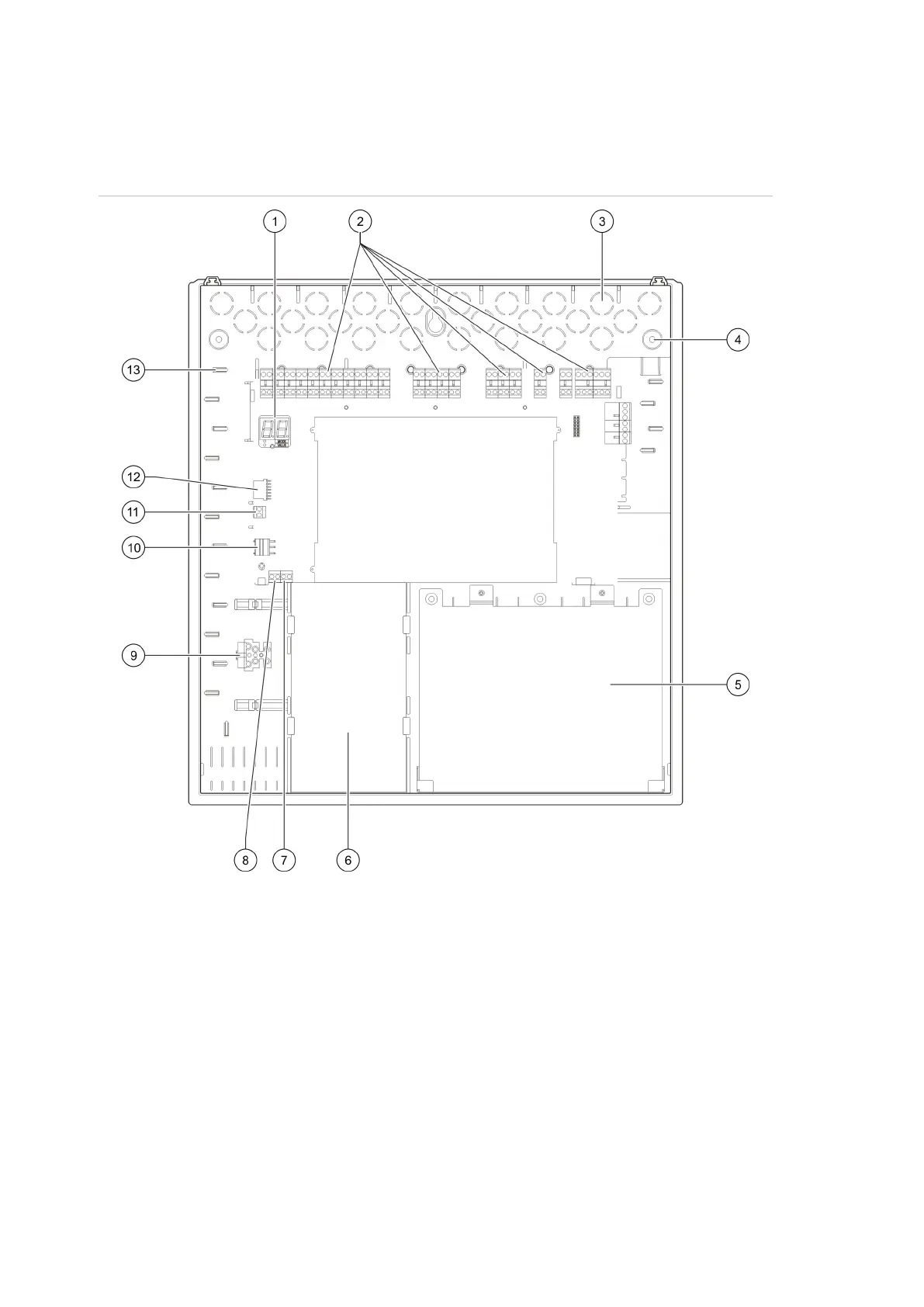
Control panel cabinet layout
Figure 1: Control panel cabinet layout
1. Seven-segment display
2. Zone, input, output, and relay connectors
3. Cable knockouts
4. Mounting screw knockouts
5. Battery area
6. Power supply unit
7. Key connector (see note)
8. MCP release connector (reserved for
future use)
9. Fuse terminal block
10. Power supply connector
11. Battery connector
12. Expansion board connector
13. Cable holder
Note: The control panel is available with an access key option. The key switch is
located on the panel cover. With this option, either the key or the password can
be used to enter the operator user level.
 Loading...