Chapter 2: Installation
10 1X-X3 Installation Manual
Connecting inputs
Input functionality
Each control panel has eight inputs, marked IN1 to IN8 on the control panel PCB.
Input functionality is shown in the table below.
Table 5: Input functionality
Input Function Supervision
IN1 Start extinguishing manual call point Supervised
IN2 Hold extinguishing manual call point Supervised
IN3 Abort extinguishing manual call point Supervised
IN4 Manual-only mode activation device Unsupervised
IN5 Low pressure indication Supervised
IN6 Extinguishing agent flow Supervised
IN7 Safety door fault monitoring Supervised
IN8 Remote reset Unsupervised
Input termination
Only supervised inputs require a 15 kΩ, 5%, 1/4 W end-of-line resistor for
termination. If a supervised input is not used, the end-of-line resistor must be
installed across the unused terminals.
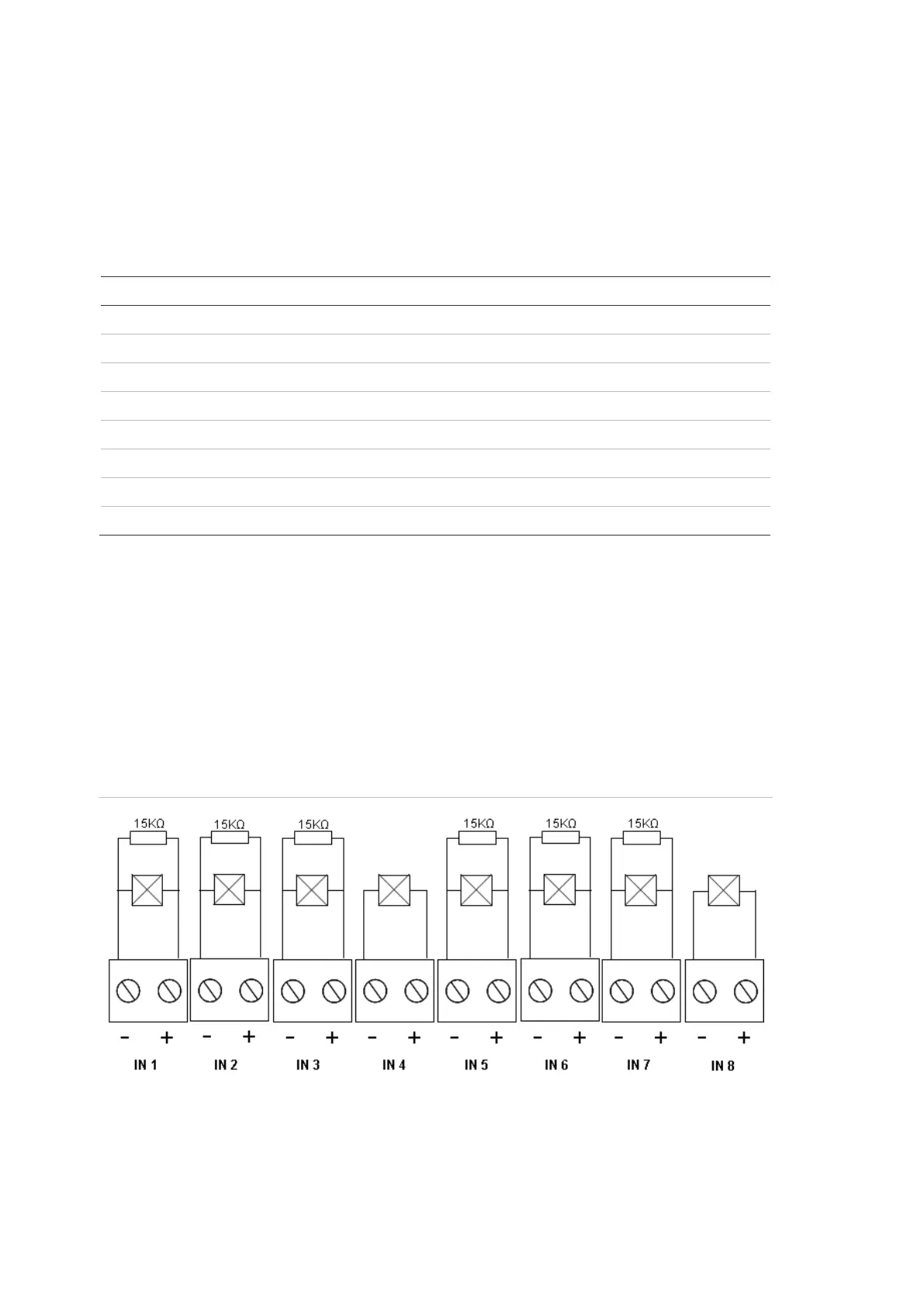
Connecting inputs
Connect inputs IN1 to IN8 as shown below.
Figure 4: Connecting inputs
Refer to the topic “Input and output specifications” on page 61 for the input circuit
parameters.
 Loading...