Chapter 2: Installation
14 1X-X3 Installation Manual
EU ordinances and regulations require the use of a key switch to control access
to this function.
The remote reset is executed when the input device switches from deactivated to
activated. Refer to the topic “Input and output specifications” on page 61 for the
impedance values for this unsupervised input.
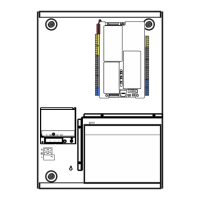
Connecting outputs
Output functionality
Each control panel has eight outputs, marked OUT1 to OUT8 on the control
panel PCB. Output functionality is shown in Table 6 below.
Table 6: Output functionality
Output Function Type and status
OUT1 Hold extinguishing manual call point Free-of-voltage (unsupervised switch)
Hold inactive = open
Hold active = closed
OUT2 Abort extinguishing manual call point Free-of-voltage (unsupervised switch)
Abort inactive = open
Abort active = closed
OUT3 Manual-only mode Free-of-voltage (unsupervised switch)
Manual-automatic = open
Manual-only = closed
OUT4 Extinguishing released Free-of-voltage (unsupervised switch)
Released inactive = open
Released = closed
OUT5 Fire sounders Supervised (standard)
Off = −11 VDC (supervision)
On = +24 VDC
OUT6 Extinguishing sounders Supervised (standard)
Off = −11 VDC (supervision)
On = +24 VDC
OUT7 Extinguishing released optical warning
panels or signs
Supervised (standard)
Off = −11 VDC (supervision)
On = +24 VDC
OUT8 Extinguishing actuator Supervised (extinguishing EOL)
Off = −11 VDC (supervision)
On = +24 VDC
Connecting free-of-voltage outputs
These outputs use the normally open (NO) and the common (C) terminals of a
relay to provide the free-of-voltage, isolated, unsupervised switch functionality.
 Loading...