Chapter 2: Installation
1X-X3 Installation Manual 19
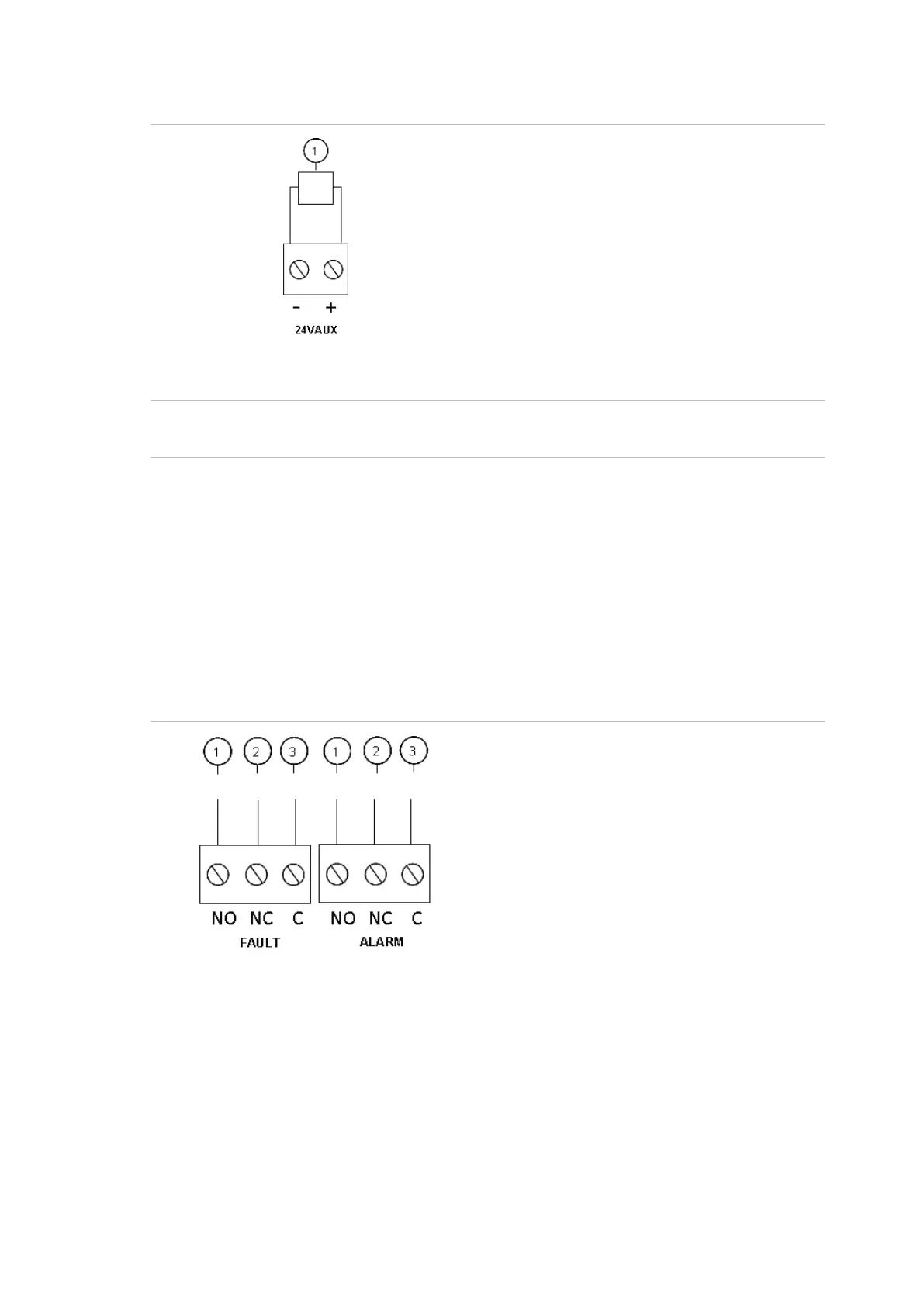
Figure 11: Auxiliary power supply output connection (24VAUX)
1. External equipment to be powered with
24 VDC
Refer to Table 22 on page 63 for the maximum current and other output ratings.
Caution: Never use the auxiliary output to power expansion boards connected to
the same control panel as this might damage the control panel hardware.
Connecting alarm and fault relays
Connect alarm and fault equipment to the ALARM and FAULT relays.
Each potential-free relay output is activated in the corresponding alarm or fault
situation. The fault relay output is activated when there is no fault. This means
that there is a short circuit between the common (C) and normally open (NO)
terminals of the relay.
The maximum contact rating for each relay circuit is 2 A at 30 VDC.
Figure 12: Fault and alarm relay output connections
1. Normally open contact
2. Normally closed contact
3. Common
 Loading...